Lanner FW-8894 User Manual
Page 15
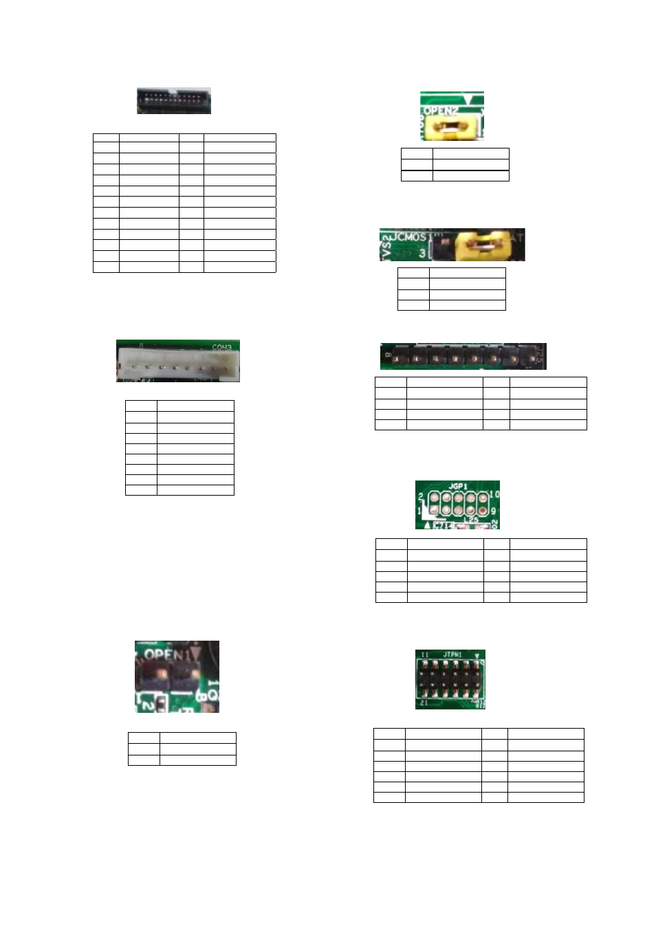
J23: LCM
CON3: PMBUS/TTL
JOPEN1: Chassis Open Detect mainboard protection
jumper. (a short-pin cap will be connected to the top
compartment of the system chassis. When the top
compartment is lifted/removed, the board functions will
be disabled once the jumper cap is lifted along with the
top compartment. This is to protect the board from being
tampered by anyone who remove the top compartment.
Pin
Description
Pin
Description
1
VCC
2
GND
3
P_SLIN_N
4
VEE
5
P_AFD_N
6
P_INIT_N
7
LPD1
8
LPD0
9
LPD3
10
LPD2
11
LPD5
12
LPD4
13
LPD7
14
LPD6
15
LCD
16
VCC
17
KPA1
18
KPA2
19
KPA3
20
KPA4
21
FP_RESET#
22
CTR_GRN
23
CTR_YEW
24
HDD_LED#
Pin
Description
1
PSU_TTL1
2
PSU_TTL2
3
4
GND
5
6
PMBUS_CLK
7
PMBUS_DAT
8
PMBUS_ALERT#
Pin
Description
1
GND
2
CSOPEN#
JOPEN2: MGT port SEL (IPMI/I210). This is the
management port function selection jumper.
JCMOS: Clear CMOS
J25: Burn CPLD (Complex Programmable Logic Device)
JGP1: External GPIO header
JTPM1: TPM connector
Pin
Description
1
MGT_SEL
2
IPMI_DETECT#
Pin
Description
1
VRTC
2
PCH_RTCRST#
3
GND
Pin
Description
Pin
Description
1
VCC
5
2
JTAG_PLD_TPO
6
JTAG_PLD_TMS
3
JTAG_PLD_TD1
7
GND
4
8
JTAG_PLD_TCK
Pin
Description
Pin
Description
1
GPO_B_1
6
GPI_B_3
2
GPI_B_1
7
GPO_B_4
3
GPO_B_2
8
GPI_B_4
4
GPI_B_2
9
GND
5
GPO_B_3
10
GND
Pin
Description
Pin
Description
1
IRQ_SERIAL
2
LPC_FRAME#
3
LPC_LAD0
4
CLK_33M_PCI
5
LPC_LAD1
6
VCC
7
LPC_LAD2
8
9
LPC_LAD3
10
VCC
11
PLT_RST#
12
GND