Lanner FW-8894 User Manual
Page 14
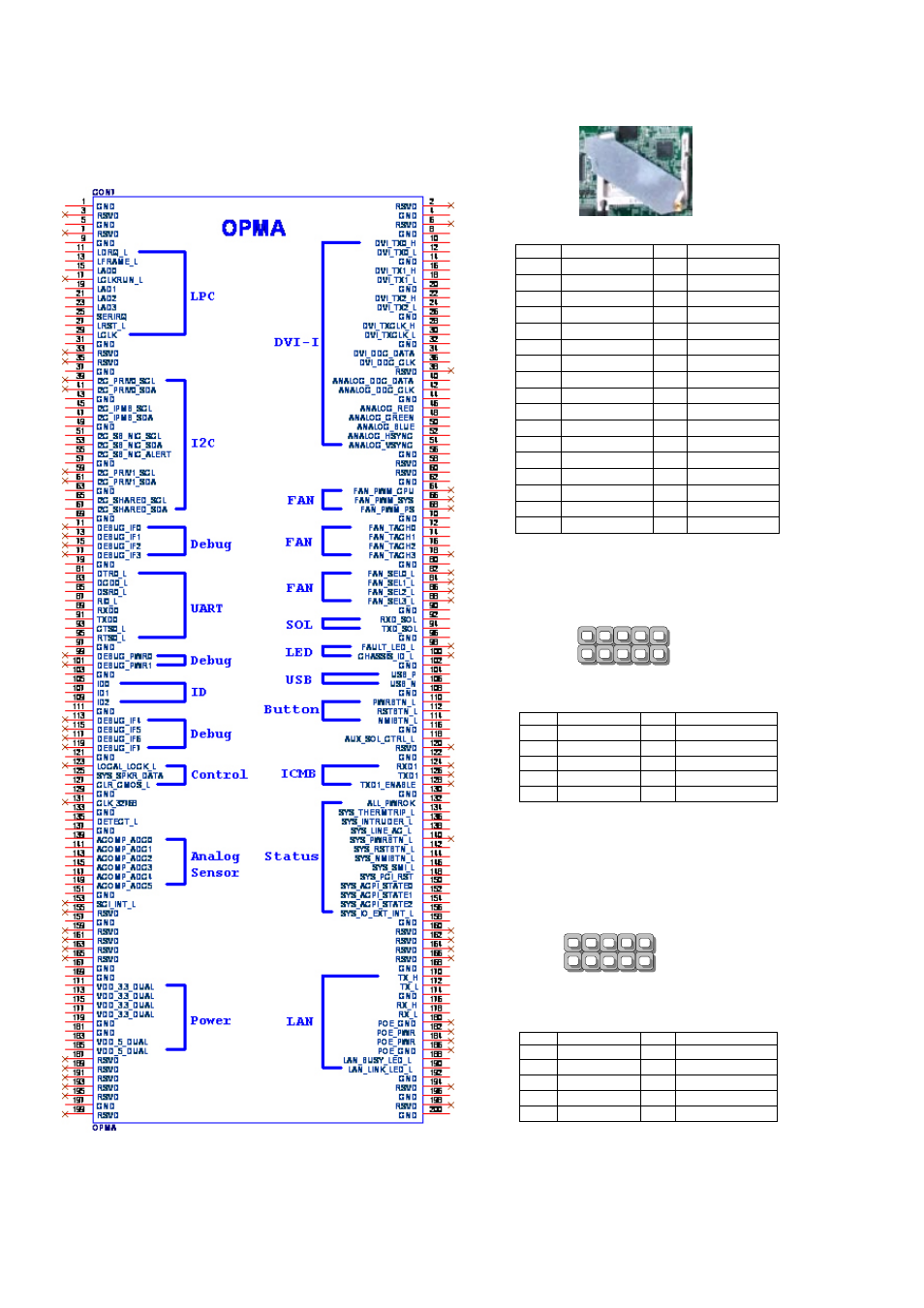
OPMA1: OPMA interface. The OPMA connector is
for connecting the OPMA card. When the OPMA card is
connected, the management port will comply with the
Intelligent Platform Management Interface (IPMI) standard.
JCFast1: CFast card
JCOMA1: COM PORT Connector
COMB1: COM PORT Internal Connector
Pin
Description
Pin
Description
1
NDCD1
2
NDSR1
3
NRXD1
4
NRTS1
5
NTXD1
6
NCTS1
7
NDTR1
8
NRI1
9
GND
10
FP_RESET_N
Pin
Function
Pin
Function
PC1
Tie to Pin17
S1
GND
PC2
GND
S2
SATA_TX_P0
PC3
S3
SATA_TX_N0
PC4
S4
GND
PC5
S5
SATA_RX_N0
PC6
S6
SATA_RX_P0
PC7
GND
S7
GND
PC8
LED_CFAST#
PC9
PC10
PC11
PC12
PC13
P3V3
PC14
P3V3
PC15
GND
PC16
GND
PC17
Tie to Pin1
Pin
Description
Pin
Description
1
NDCD2-
2
NDSR2-
3
NRXD2
4
NRTS2-
5
NTXD2
6
NCTS2-
7
NDTR2
8
NRI2-
9
GND
10
2
10
9
1
COMA1
2
10
9
1
COMB1
See also other documents in the category Lanner Computer hardware:
- LVC-2000 (39 pages)
- LVC-5000(N4) (42 pages)
- LVC-5550S (41 pages)
- LVC-5570 (48 pages)
- LVC-5770 (49 pages)
- FW-6432 (16 pages)
- FW-7525 (41 pages)
- FW-5330 (38 pages)
- FW-6486 (18 pages)
- FW-6436 (19 pages)
- FW-7573 (44 pages)
- FW-7568 (52 pages)
- FW-7540 (47 pages)
- FW-8759 (47 pages)
- FW-7581 (23 pages)
- FW-8758 (42 pages)
- FW-7610 (44 pages)
- FW-8756 (24 pages)
- FW-7575 (48 pages)
- FW-8760 (53 pages)
- FW-8877 (46 pages)
- FW-8892 (58 pages)
- FW-8893C (49 pages)
- FX-3411 (48 pages)
- FW-8771 (47 pages)
- RS12-38800 (64 pages)
- MR-320 (20 pages)
- FX-3210 (54 pages)
- MR-301 (16 pages)
- MR-350 (12 pages)
- MR-330A (16 pages)
- MR-730 (18 pages)
- VES-220 (19 pages)
- VES-270 (19 pages)
- VES-310 (15 pages)
- VES-310 V2 (20 pages)
- VES-500 (21 pages)
- EM-F345 (30 pages)
- VES-8X2 (16 pages)
- VES-8X6 (17 pages)
- LEC-2026 (67 pages)
- LEC-2010 (65 pages)
- LEC-2136 (20 pages)
- LEC-2050 (38 pages)