Chapter 3, Motherboard information – Lanner FW-8760 User Manual
Page 20
15
Motherboard Information
Chapter 3
Network Application Platforms
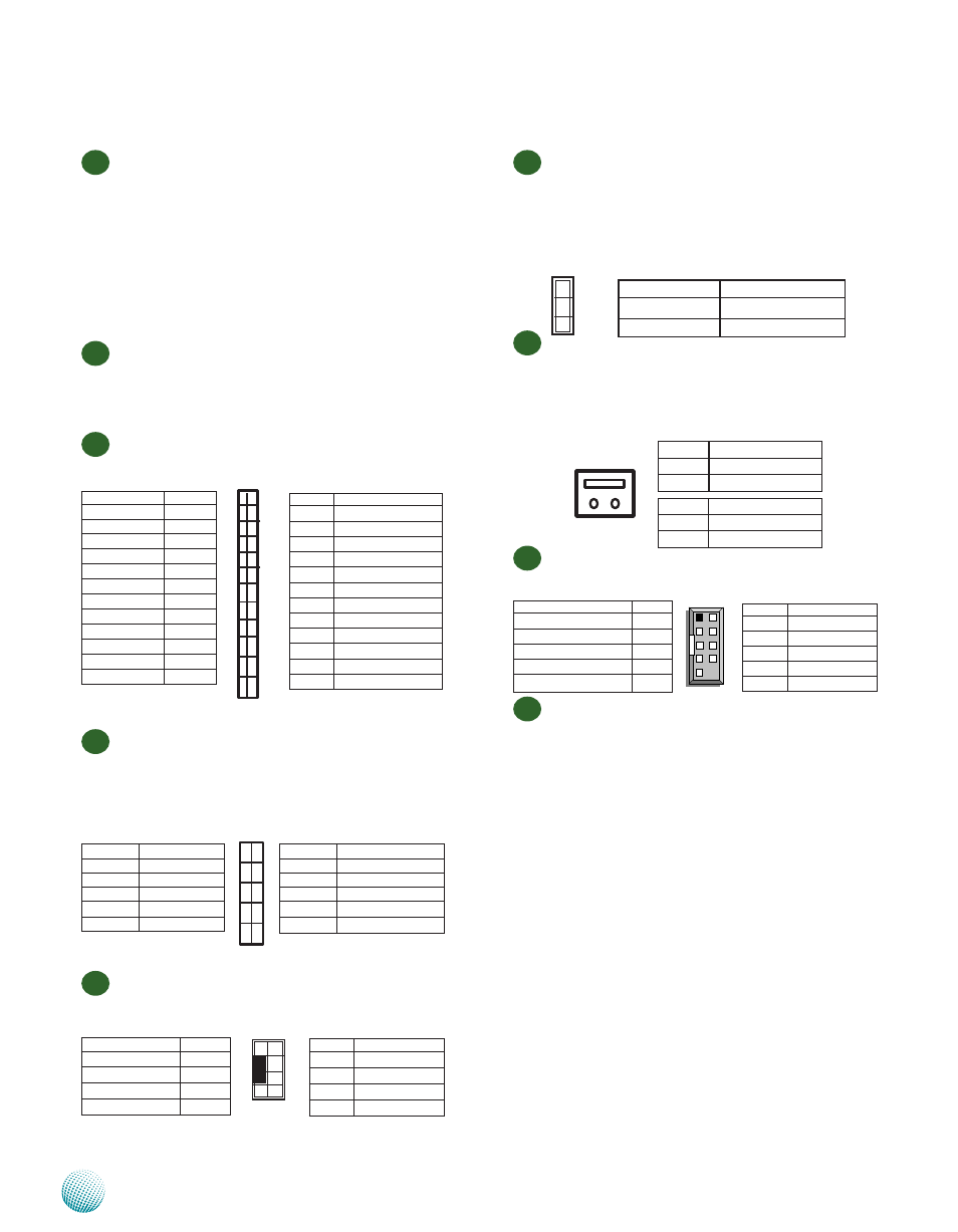
M22
LPC I/O bus (It can also be called Port 80) (LPC1): It is
a proprietary connector for connecting a checkpoint
device to output checkpoints throughout booting
and Power-On Self Test (POST) to indicate the task
the system is currently executing.
M23
Keyboard and mouse interface Connectors(PKMB1):
It is for connecting the PS/2 keyboard and mouse
interface cable.
M24
Hardware or Software Reset Jumper(J19): The jumper
can be adjusted to be in either hardware or software
reset mode when the reset switch is pressed. The
hardware reset will reboot the system without turning
off the power. The software reset can be programmed
to reset a software to its default setting.
M25
Power Failure Detection Jumper (TTL1/TTL2): This
two-pin jumper can be used for power failure
detection. Connect the redundant power 1 and
redundant power 2 to TTL1 and TTL2 respectively in
order to monitor the availability of them.
M26
Serial Interface Connectors(COMB2): It is for
connecting the RS-232 serial port interface cable.
M27
These eight Gigabit Ethernet ports are provided by
the Intel 82574L. Here is the list of capabilities that
comes with the module.
Compliant with the 1 Gb/s Ethernet 802.3 802.3u
•
802.3ab specifications
Multi-speed operation: 10/100/1000 Mb/s
•
10/100/1000 Mbps auto-negotiation
•
Manageability
Features
including
Advanced
•
Configuration and Power Interface (ACPI), Wake on
LAN* (WoL), and Preboot Execution Environment
(PXE)
Dynamically tests and reports network problems (error
•
rate, cable length) and automatically compensates
for cable issues (cross-over cable, wrong pin-out/
polarity)
Supports 9018 Byte Jumbo Frames
•
Gigabit MAC/PHY Performance Features such as MSI-X
•
support with the following benefits:
Minimizes the overhead of interrupts
Allows load balancing of interrupt handling between
different cores/CPUs
M19
VGA Interface (VGAA2) for OPMA: The VGAA2
connector is only used when OPMA is connected.
This 2X6 pin header is used to connect with the
Mini-PCI graphic card by using a VGA cable (a 2x6
to 2x6 intereface cable) to VGAA1. Then, connect the
system’s VGA interface cable (The 2x6 to female DB-
15 VGA cable) to provide a VGA port for displaying
video images. Connect a VGA-compatible display to
the female DB15 connector on its free end.
M20
OPMA Slot (IPMI1): This is an optional OPMA (Open
Platform Management Architecture ) slot on the
board. Through this card, the IPMI (Intelligent Platform
Management Interface) implementation can be realized.
M21
Front LCD Module Connector(J16): The 24-pin
connector is for connecting the front system panel.
1
3
5
7
9
2
4
6
8
10
Pin NO.
Function
2
Data Set Ready
4
Request to Send
6
Clear to Send
8
Ring Indicator
10
Key
Function
Pin No.
Data Carrier Detected
1
Received Data
3
Transmitted Data
5
Data Terminal Ready
7
Signal Ground
9
Pin No.
Function
2
MSCLK
6
KEY
6
KEY
8
KBCLK
Function
Pin No.
P5V
1
MSDATA
3
KBDATA
5
GND
7
2
4
6
8
1
3
5
7
1
2
3
Pin No.
Function
1-2
Hardware Reset
2-3 (Default)
Software Reset
Pin No.
Function
9
LPC_AD2
7
LPC_AD3
5
LPC_FRAME_N
3
RST_80DGPT_N
1
CLK_33M_P80
Pin No.
Function
10
GND
8
GND
6
+3.3V
4
LPC_LAD0
2
LPC_LAD1
10
8
6
4
2
9
7
5
3
1
Pin No.
Function
1
GND
2
RDPW_TTL1_GP36
1 2
Pin No.
Function
1
GND
2
RDPW_TTL2_GP37
Function
Pin No.
P5V
1
LPT17
3
LPT14
5
LPT3
7
LPT5
9
LPT7
11
LPT9
13
LCD-
15
KPA1
17
KPA3
19
LCM_RST
21
CTR_RED
23
Pin No.
Function
2
IOGND
4
VEE
6
LPT16
8
LPT2
10
LPT4
12
LPT6
14
LPT8
16
P5V
18
KPA2
20
KPA4
22
CTR_GRN
24
HDD_LED-
1
3
5
7
9
11
13
15
17
19
21
23
2
4
6
8
10
12
14
16
18
20
22
24