Motherboard layout, Chapter 3, Motherboard information – Lanner FW-8760 User Manual
Page 16: Network application platforms
11
Motherboard Information
Chapter 3
Network Application Platforms
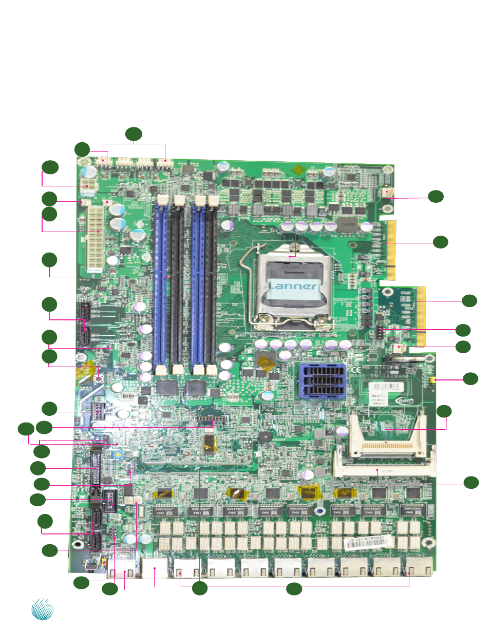
PCI-E expansion
connector (PCIEC1)
Motherboard Layout
The motherboard layout shows the connectors and
jumpers on the board. Refer to the following picture
as a reference of the pin assignments and the internal
connectors.
FAN 6
Ethernet Ports
DIMM Socket
(J1/J2/J3/J4)
Mini PCI
C o n n e c t o r
(PCIB1)
Power Switch
F A N 1 F A N 2 F A N 3 F A N 4
USB
Connector
VGA
Selection
Jumper
M4
PCI-E expansion
connector (PCIEC2)
USB Ports
Console Port
FAN 5
M5
M2
M6
CompactFlash
Card
connector (CF1)
M7
M2
M3
M3
SPI-ROM
update
Connector
M14
CMOS (J6)
A T X P o w e r
C o n n e c t o r
A T X 1
A T X P o w e r
C o n n e c t o r
A T X 2
Keyboard & Mouse
M22
M26
SATA2
SATA1
Front
LCD
Connector
LPC
M11
M15
M10
M12
SATA4
SATA3
M16
VGA
Connec tor
M21
M8
AT Mode
Jumper
AT Mode
Power Button
Connector
M9
M13
M24
M14
M25
TTL1/TTL2
M23
M27
M1
M17
M18
VGAA2
M19
Serial Port
M20
OPMA Slot
Reset Jumper