Chapter 3, Motherboard information – Lanner FW-8760 User Manual
Page 18
13
Motherboard Information
Chapter 3
Network Application Platforms
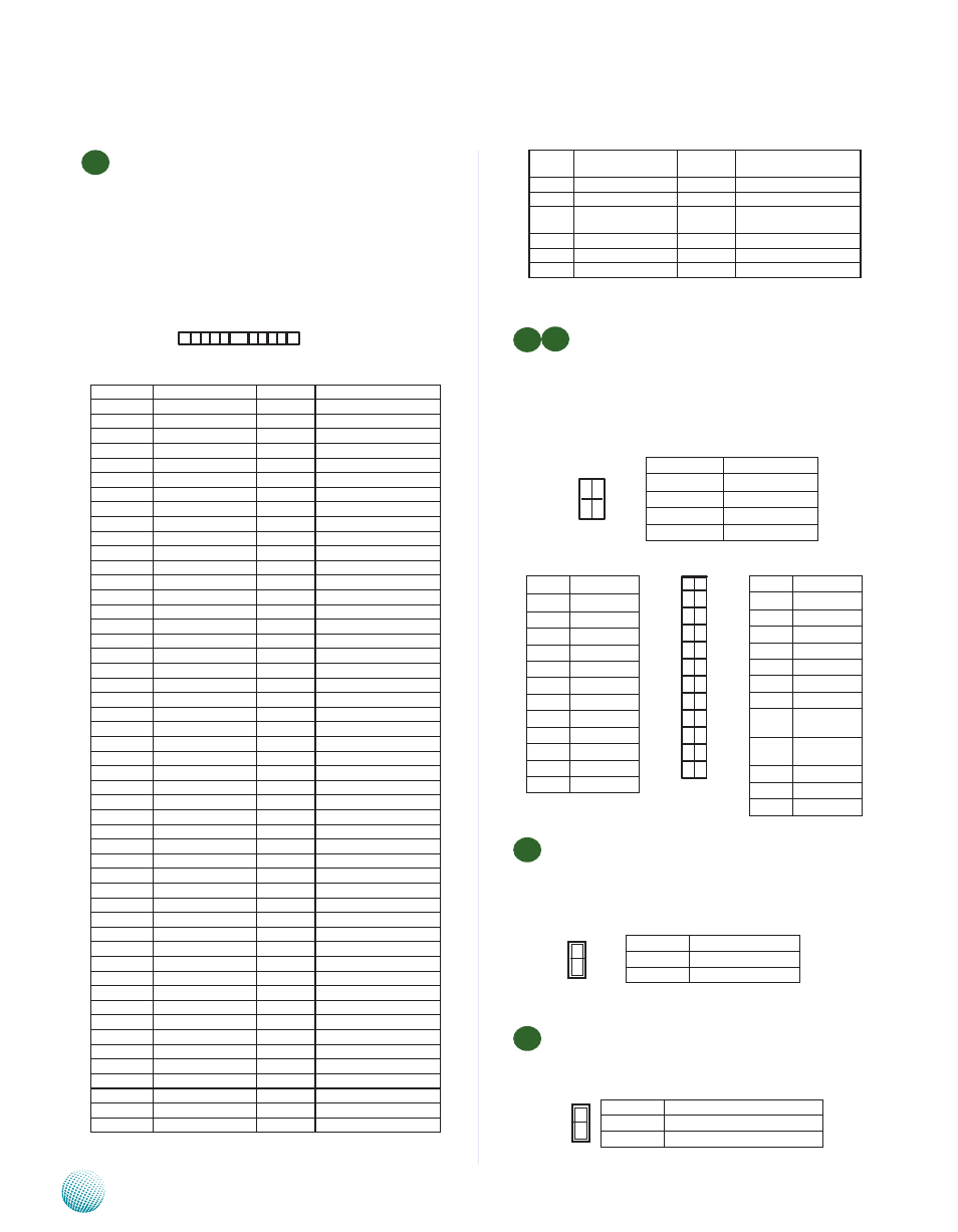
M8
M9
ATX Power Connector(ATX1, ATX2): These 24-
pin and 4-pin connectors are for connecting ATX
power supply plugs. Find the proper orientation
when inserting the plugs, for the supply plugs
are designed to fit these connectors in only one
orientation.
M10
AT Mode Power Button Connector (J17): It is for
connecting the power switch in AT mode
.
M11
AT Mode Jumper(J8): It is for adjusting the jumper
setting for the system power to be in ATX mode if AT
Mode Power Button Connector (J17) is used.
M7
Mini-PCI Connector (PCIB1): The Mini-PCI slot enables
a Mini-PCI expansion module to be connected to the
board. If the processor which you choose is Lynnfield
Xeon processor , you would first install the VGA Card
to this connector.
PIN NO.
FUNCTION
PIN NO.
FUNCTION
1
TIP
2
RING
3
8PMJ-3
4
8PMJ-1
5
8PMJ-6
6
8PMJ-2
7
8PMJ-7
8
8PMJ-4
9
8PMJ-8
10
8PMJ-5
11
LED1_GRNP
12
LED2_YELP
13
LED1_GRNN
14
LED2_YELP
15
CHSGND
16
RESERVED
17
INT-B
18
+5V
19
+3.3V
20
INT-A
21
RESERVED
22
RESERVED
23
GROUND
24
3.3VAUX
25
CLK
26
RST
27
GROUND
28
+3.3V
29
REO
30
GNT
31
+3.3V
32
GROUND
33
AD31
34
PME
35
AD29
36
RESERVED
37
GROUND
38
AD30
39
AD27
40
+3.3V
41
AD25
42
AD28
43
RESERVED
44
AD26
45
C_BE-3
46
AD24
47
AD23
48
IDSEL
49
GROUND
50
GROUND
51
AD21
52
AD22
53
AD19
54
AD20
55
GROUND
56
PAR
57
AD17
58
AD18
59
C_BE-2
60
AD16
61
IRDY
62
GROUND
63
+3.3V
64
FRAME
65
CLKRUN
66
TRDY
67
SERR
68
STOP
69
GROUND
70
+3.3V
71
PERR
72
DEVSEL
73
C_BE-1
74
GROUND
75
AD14
76
AD15
77
GROUND
78
AD13
79
AD12
80
AD11
81
AD10
82
GROUND
83
GROUND
84
AD9
85
AD8
86
C_BE-0
87
AD7
88
+3.3V
89
+3.3V
90
AD6
91
AD5
92
AD4
93
RESERVED
94
AD2
95
AD3
96
AD0
97
+5V
98
RESERVED-WIP
99
AD1
100
RESERVED-WIP
1 124
111
M O D _ A U D I O _
MON
112
RESERVED
113
AUDIO_GND
114
GROUND
115
SYS_AUDIO_OUT
116
SYS_AUDIO_IN
117
SYS_AUDIO_OUT
GND118
118
SYS_AUDIO_IN GND
119
AUDIO_GND
120
AUDIO_GND
121
RESERVED
122
MPCIACT
123
VCC5VA
124
3.3AUX
1 2
3 4
Pin No.
Function
1
GND
2
+12V
3
GND
4
+12V
1
3
5
7
9
11
13
15
17
19
21
23
2
4
6
8
10
12
14
16
18
20
22
24
Pin No.
Function
2
+3.3V
4
-12V
6
GOUND
8
PSON-
10
GROUND
12
GROUND
14
GROUND
16
NC
18
+5V
20
+5V
22
+5V
24
GROUND
Pin No.
Function
1
+3.3v
3
+3.3v
5
GROUND
7
+5V
9
GROUND
11
+5V
13
GROUND
15
P O W E R
GOOD
17
S T A N D - B Y
5V
19
+12V
21
+12V
23
+3.3V
1
2
Pin No.
Function
--
Normal (Default ATX Mode)
1-2
AT mode
2
1
Pin No.
Function
1
PS_ON#
2
GND