Chapter 3, Motherboard information – Lanner FW-8760 User Manual
Page 19
14
Motherboard Information
Chapter 3
Network Application Platforms
Note: To configure your Hard disk using the
integrated RAID feature, the Intel® Matrix
Storage Manager software has to be installed on
your Operating System. Visit the Intel support
page at
or more
information and download links.
The Intel controller hubs are also supported
by Linux. Beginning with Linux kernel version
2.6.27, the mdadm utility 3.0 supports RAID 0,
RAID 1, RAID 10, and RAID 5.
To use the RAID features in dmraid and mdadm,
you will need to set up the RAID volume using
the Intel® Matrix Storage Manager option ROM
(click CTRL + I when prompted during boot to
enter the option ROM user interface).
M15
Power-switch on board (SW1): A tact is used for
turning on or off the power once the power supply is
applied to the board.
M16
USB Connector(J12) : It is for connecting the USB
module cable. It complies with USB2.0 and support
up to 480 Mbps connection speed.
M17
VGA Interface (VGAA1): It is for connecting the VGA
interface cable (2X6 pin to female DB15 connector)
.
M18
VGA Signal Selection Jumper (BPS1/BPS2): Use this
jumper to select the source of the VGA signal from
either processor graphics or external graphics. You
only need to adjust this jumper when using the
Lynnfield Xeon processor in which a Mini-PCI graphic
card is present.
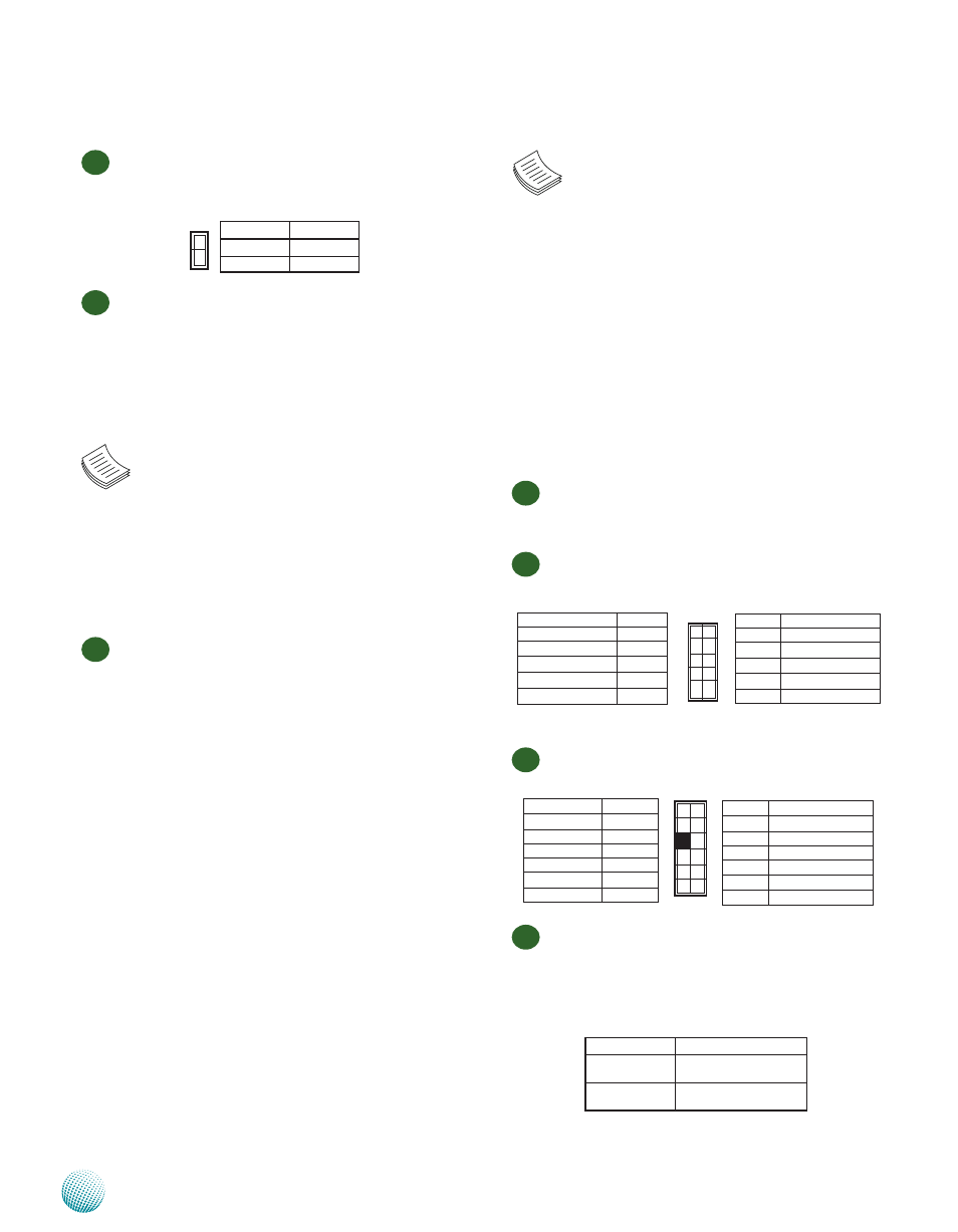
M12
Power Button Connector(CONN2): It is for connecting
the cable of the system power switch ( in ATX mode)
on the back panel.
M13
DIMM Socket (J1/J2/J3/J4): The 240-pin DDR3 DIMM
is for connecting the DDR3 1066/1333 (unbuffered
ECC or non-ECC) memory. The system can support
up to16 GB in maximum. A DDR3 module has the
same physical dimensions as a DDR2 DIMM but the
notch on the pins is positioned differently to prevent
installation on a DDR2 DIMM socket.
Note: Since the system is capable of Dual
Channel Architecture, some installation
guidelines have to be met to enable Dual
Channel mode as directed. To insert two DIMMs
on the system, insert DIMMS on slot J1 (blue)
and J3 (blue). And use slot J2 (black) and J4
(black) if more than one slot is required. (Use
slot J2 and then slot J4 in sequence for the
additional DIMMS.)
M14
SATA 1, 2 and 3, 4 Connectors (SATA1/SATA2/
SATA3/SATA4): It is for connecting a 2.5’’ SATA
harddisk to be served as your system’s storage. The
system can accommodate up to 2 disks (2.5" or
1disk for 3.5") in maximum. The SATA controller
complies fully with SATA Revision 2.0 standard
which supports independent DMA operation on up
to 4 ports and data transfer rates of up to 3.0 GB/s
(300 MB/s). The controller contains two modes of
operation—a legacy mode using I/O space, and an
AHCI mode using memory space. Software that
uses legacy mode will not have AHCI capabilities.
The AHCI ( Advanced Host Controller Interface) is a
programming interface which defines transactions
between the SATA controller and software and
enables advanced performance and usability with
SATA. Platforms supporting AHCI may take advantage
of performance features such as no master/slave
designation for SATA devices—each device is treated
as a master—and hardware assisted native command
queuing. AHCI also provides usability enhancements
such as Hot-Plug. Here is the list of the AHCI capabilities
which exist in the system:
Hardware assisted native command queuing
1.
Aggressive power management
2.
LED indicator support
3.
1
2
Pin No.
Pin name
1
GND
2
PS_ON#
Pin No.
Function
9
USB Port Ground
7
Ground
5
USBD0+
3
USBD0-
1
USB_VCC
Pin No.
Function
USB D1 Ground
10
Ground
8
USBD1+
6
USBD1-
4
USB_VCC
2
9
7
5
3
1
10
8
6
4
2
Pin No.
Function
11
DDC-Data
9
VSYNC
7
HSYNC
5
Blue
3
Green
1
Red
Function
Pin No.
DDCCLK
12
GND
10
Key
8
GND
6
GND
4
GND
2
11
9
7
5
3
1
12
10
8
6
4
2
Jumper Name
Function
BPS1
Selecting Mini-PCI VGA
signal
BPS2
Selecting onboard VGA
signal (default)