Chapter 2, System components, Front components – Lanner LVC-5000(N4) User Manual
Page 9
9
System Components
Chapter 2
Embedded and Industrial Computing
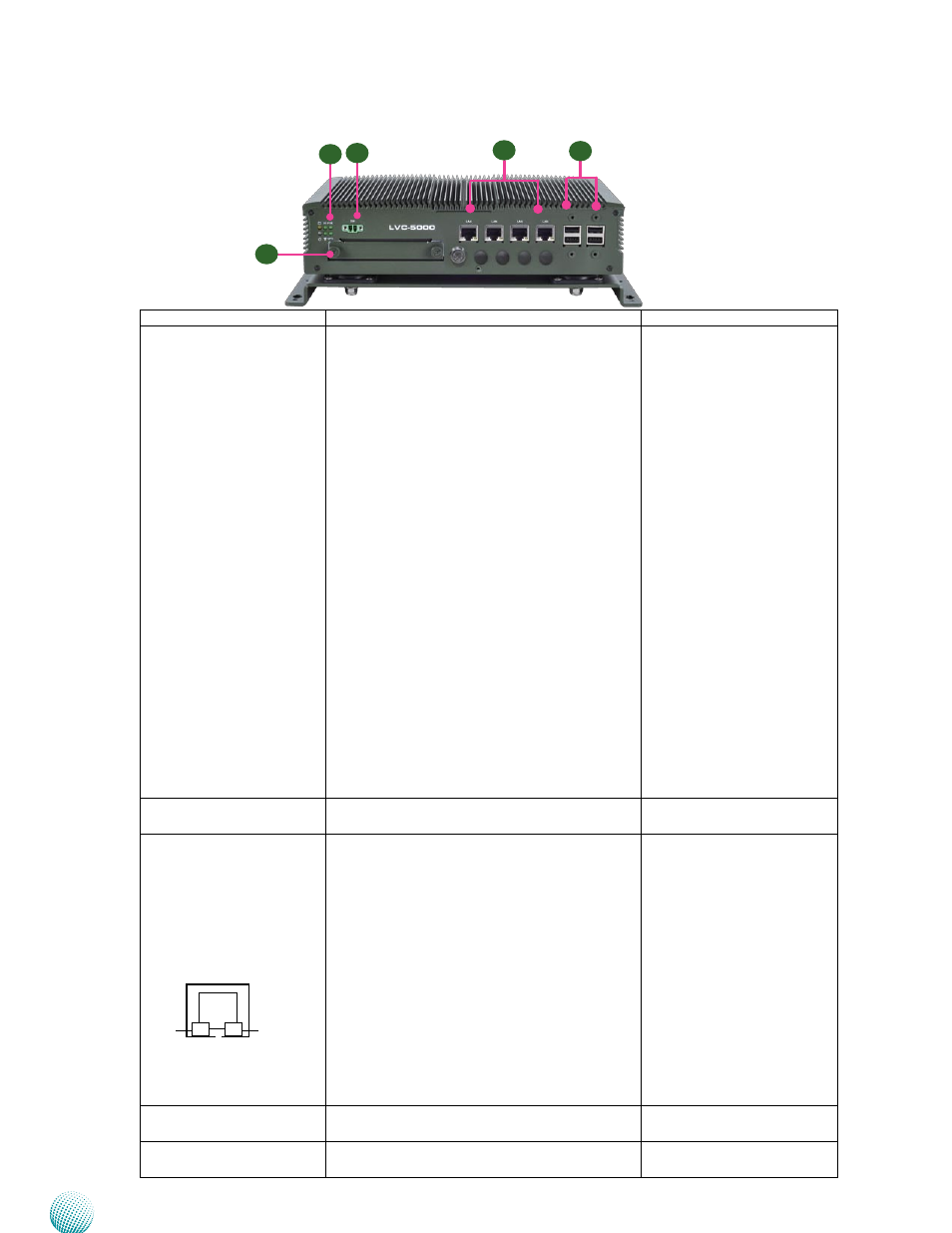
Front Components
F1
F5
F2
F3
F4
LINK/ACT
SPEED
Component
Description
Pin Definition Reference
F1 HDD/SSD (Yellow) and
Power LED (Green)
HDD/SSD
Blinking: means data access activities
•
Off: means no data access activities or no
•
hard disk present
Power
On: The computer is on.
•
Off: The computer is off .
•
3G/4G
Blinking: The 3G service is active. (*)
•
Off: The 3G service is not active. (*)
•
WiFi
On: The Wi-Fi service is active. (*)
•
Off: The Wi-Fi service is not active. (*)
•
POE (indicator for POE 48V input via LVK-
POE60W01)
On: The POE function is active.
•
Off: The POE function is not active.
•
GPO (indicator for GPIO function on ignition
status)
On: The ignition has been turned on.
•
Off: The ignition has not been turned on.
•
F2 Remote Power Switch
1x2-pin terminal block for distant power-on/off
control
CN3 on page 21
F3 Four 10/100/1000Mbps
LAN ports
Four RJ-45 (provided by Intel 82583V) jacks with
LED indicators as described below
LINK/ACT (Yellow)
On/Flashing: The port is linking and active
•
in data transmission.
Off: The port is not linking.
•
SPEED (Green/Amber)
Amber: The connection speed is 1000Mbps.
•
Green: The connection speed is 100Mbps
•
Off: The connection speed is 10Mbps.
•
They are provided by Intel 82583V GbE chips
with Power over Ethernet power source
capability (48V, 15.4W).
LANB1/LANB2/LANB3/LANB4
on page 21
F4 Four USB 2.0 Ports
USB type A connectors; additional 2 ports with
pin headers
Dual USB Port #0, #1 and #2,
#3 (USBB1,USBB2) on page 21
F5 2.5” Storage Drive Bay
with Lock (†)
Removable 2.5” storage drive for easy replace-
ment of the storage
SATAB1 on page 18