Chapter 4, Chapter 4: the flow chart, Flow chart – Lanner LVC-5000(N4) User Manual
Page 23
23
Flow Chart
Chapter 4
Embedded and Industrial Computing
Chapter 4:
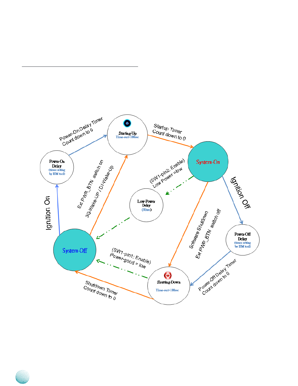
The Flow Chart
The flow chart section contains all flow chart used in the
system. The flow chart describes the system’s behavior on
powering on and off the system via power ignition control
or on/off switch when the appropriate timer control
parameters are set.
Note:
For power-good and low-voltage
1.
mechanism to function in the workflow,
you will need to enable the power-good
and low-voltage detection function
with selector 1 and selector 2 jumper
respectively of SW1. (Refer to Chapter 3
Board Layout).
For power on and power off delay timer
2.
parameter, refer to Appendix A Using the
Ignition System Manager (ISM).
For DI wake-up function, refer to jumper
3.
MIO2 Pin NO.19 and 21. Refer to Chapter
3 Board Layout and Appendix A Using
the Ignition System Manager (ISM) for
jumper setting and parameter setting
respectively.
When the system’s shutdown timer starts
4.
counting down 180sec, using ignition
or External PWR_BTN to start the system
again during shutdown process will not
work until the countdown finishes.