Chapter 3, Board layout, Sct1 – Lanner LVC-5000(N4) User Manual
Page 17
17
Board Layout
Chapter 3
Embedded and Industrial Computing
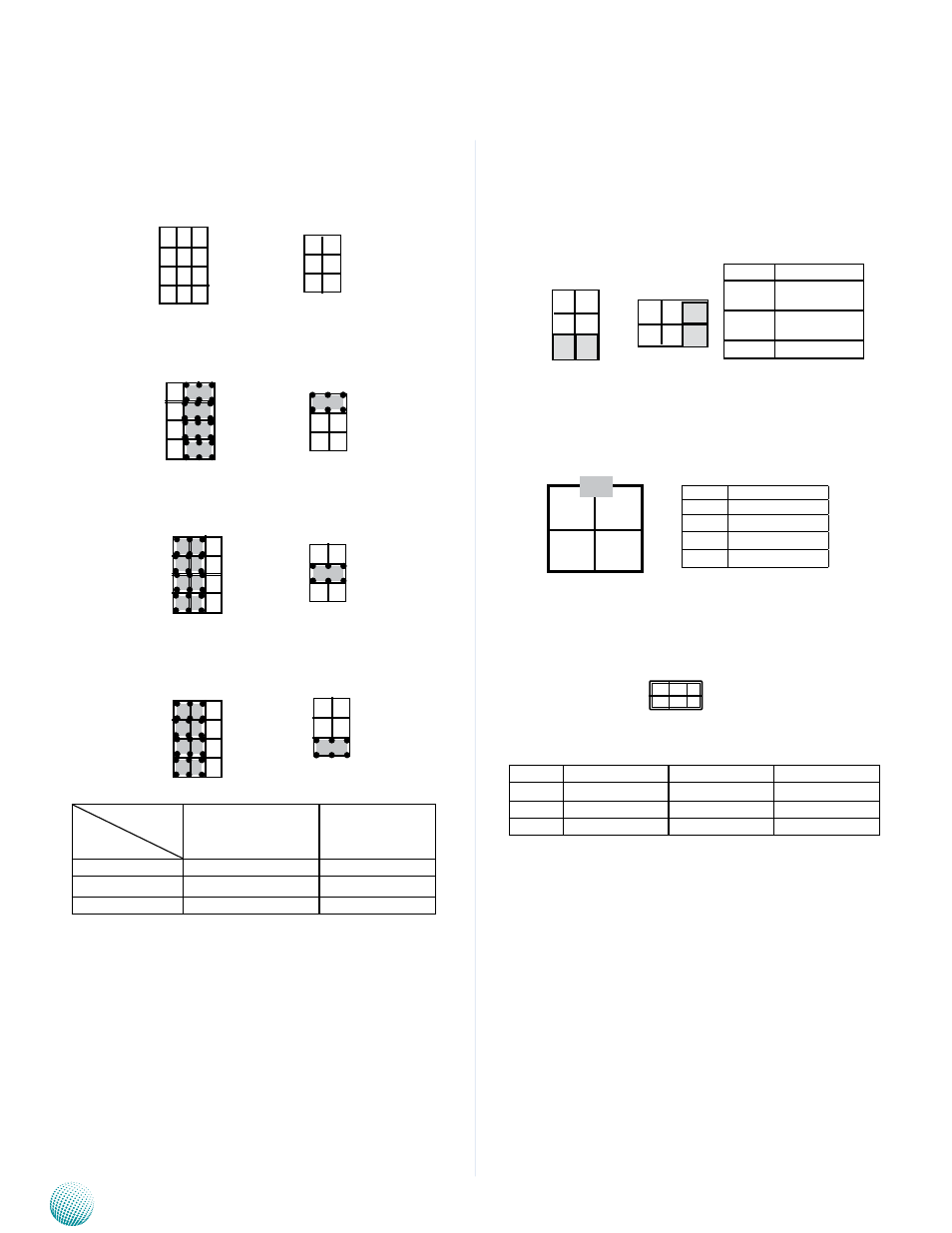
SCT1, SCT2: Select COM2 Protocol Setting
RS-232
RS-422
RS-485
Switch
Protocol
SCT1
SCT2
RS-232 (default)
1-5, 2-6, 3-7, 4-8
1-2
RS-422
5-9, 6-10, 7-11, 8-12
3-4
RS-485
5-9, 6-10, 7-11, 8-12
5-6
12
11
10
9
4
3
2
1
SCT2
2
4
6
1
3
5
SCT1
4
3
2
1
12
11
10
9
1
2
PCOM1, PCOM2: Select COM1 and COM2 Pin9 Function
(in RS-232) respectively. The Ring indicator pinout of
the RS-232 COM port can be altered according to the
following jumper settings.
PS4M1: Connect to the ATX1 power connector on the
LVK-POE60W01 board
AUDIOIN1: Line-in and Mic-in Connector
Pin No.
Function
1-2
Supply +5V to
the Device
3-4
Supply +12V to
the Device
5-6
Ring-in (default)
2 4 6
PCOM1
2
4
6
1
3
5
1 3 5
PCOM2
Pin No.
Pin Name
1
GND
2
DC_VIN (9-36V)
3
GND
4
DC_VIN (9-36V
2 1
4 3
Pin No.
Pin Name
Pin No.
Pin Name
1
MIC_in_R
2
MIC_in_L
3
Audio_in_R
4
Audio_in_L
5
Line_in1_R
6
Line_in1_L
1 3 5
2 4 6
- LVC-2000 (39 pages)
- LVC-5550S (41 pages)
- LVC-5570 (48 pages)
- LVC-5770 (49 pages)
- FW-6432 (16 pages)
- FW-7525 (41 pages)
- FW-5330 (38 pages)
- FW-6486 (18 pages)
- FW-6436 (19 pages)
- FW-7573 (44 pages)
- FW-7568 (52 pages)
- FW-7540 (47 pages)
- FW-8759 (47 pages)
- FW-7581 (23 pages)
- FW-8758 (42 pages)
- FW-7610 (44 pages)
- FW-8756 (24 pages)
- FW-7575 (48 pages)
- FW-8760 (53 pages)
- FW-8877 (46 pages)
- FW-8892 (58 pages)
- FW-8893C (49 pages)
- FX-3411 (48 pages)
- FW-8894 (31 pages)
- FW-8771 (47 pages)
- RS12-38800 (64 pages)
- MR-320 (20 pages)
- FX-3210 (54 pages)
- MR-301 (16 pages)
- MR-350 (12 pages)
- MR-330A (16 pages)
- MR-730 (18 pages)
- VES-220 (19 pages)
- VES-270 (19 pages)
- VES-310 (15 pages)
- VES-310 V2 (20 pages)
- VES-500 (21 pages)
- EM-F345 (30 pages)
- VES-8X2 (16 pages)
- VES-8X6 (17 pages)
- LEC-2026 (67 pages)
- LEC-2010 (65 pages)
- LEC-2136 (20 pages)
- LEC-2050 (38 pages)