Chapter 3, Board layout, Connectors and jumpers list – Lanner LVC-5000(N4) User Manual
Page 15
15
Board Layout
Chapter 3
Embedded and Industrial Computing
Connectors and Jumpers List
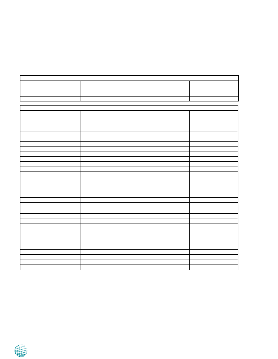
The tables below list the function of each of the board
jumpers and connectors by labels shown in the above
section. The next section in this chapter gives pin
definitions and instructions on setting jumpers.
Table 3.1 Connector List for LVK-POE60W01 Board
Labels
Function
Pin Definition Refer-
ence Page
ATX1
ATX Power Connector
P16
POEIO1
Connector for connecting to the mainboard
p16
Table 3.2 Connector List for LEB-5000 Board
Labels
Function
Pin Definition Refer-
ence Page
AUDIOIN1
Line-in/Mic-in Connector
P17
CMOS1
Cleaning CMOS Data Including RTC
P21
CF1
CF Card Slot
P19
CN2
RS-232 Connector for MCU Programming
P22
CN3
Distant Power on/off Control Connector
P21
CN5
12VDC Power Output
P22
COMB1/COMB2
RS232/422/485 Serial Port
P16
DVID1
DVI-D Connector
P19
FAN1
System Fan Connector
P19
SPI1
Serial Peripheral Interface Bus
Reserved for factory use
HDMI1
HDMI Port
P19
LANB1/LANB2/LANB3/LANB4 Ethernet Connector 1~4
P21
LPC1
Low Pin Count Interface
Reserved for factory use
MIO2
Proprietary Board-to-Board connector for multiple re-
served function
P20
MIO3
Mini PCI Express Connector (MIO3)
P18
MPCIE1/MPCIE2
Mini-PCIe Connector 1 & 2
P20
PCOM1/PCOM2
Select COM1/COM2 Pin9 Function
P17
PKMB1
PS/2 Keyboard and Mouse Connector
p22
PRJK1
DC-in with Ignition Control
P21
POEIO1
POE board LVK-POE60W01 connectors
P19
PS4M1
Connector for connecting ATX1 on LVK-POE60W01
P17
PS4S1
SATA Power
P18
SATAB1
Serial-ATA Connector
P18
SCT1/SCT2
Select COM2 Protocol Setting
P17
SIM1/SIM2
SIM Card Readers
P21
SW1
Power Control Function Selection
P22
USBB1/USBB2
USB Type A Connector #0,1; #2,3
P21
VGAA1
VGA Port
P19