6 electrical connection, Warning, General information – KACO blueplanet 1502xi User Manual
Page 34
Page 31
31
31000770-02-112609 blueplanet Operating and Installation Instructions 1502xi - 5002xi
240V
180°
L1
L2
=
~
120V
120V
N
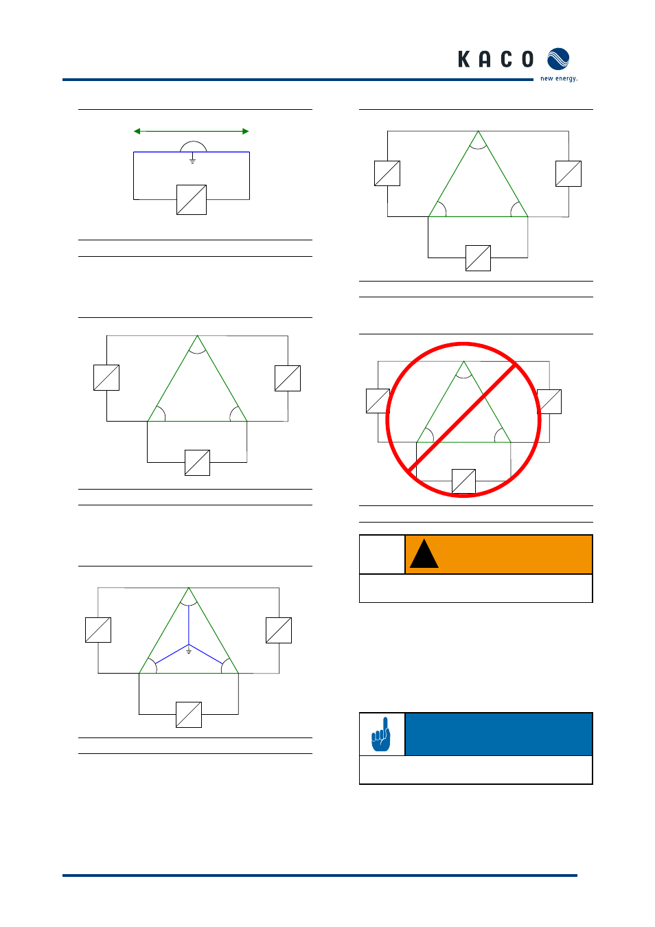
Figure 5.12: 240/120 V Split Phase
Country setting on the display: USA 240 V
L1
L2
L3
120°
120°
120°
~
=
~
=
~
240V
240V
240V
=
Figure 5.13: 240 V Delta
Country setting on the display: USA 240 V no neut
L1
L2
L3
120°
120°
120°
~
=
~
=
~
208V
208V
208V
120V
120V
120V
N
=
Figure 5.14: 208V/120V WYE
Country setting on the display: USA 208V
L1
L2
L3
120°
120°
120°
~
=
~
=
~
208V
208V
208V
=
Figure 5.15: 208V Delta
Country setting on the display: USA 208V no neut
L1
L2
L3
120°
120°
120°
~
=
~
=
~
480V
480V
480V
=
Figure 5.16: 480V Delta or 480/277V WYE
!
WARNING
Do not connect the inverter to the 480 V Delta or
480V/277V WYE power grids.
5.6 Electrical connection
General information
The electrical connections can be established after the inverter
is installed in its fixed location. Knockouts are provided on the
sides, bottom, and rear of the connection box to easily run
conduit to the desired locations.
NOTE
Only conduit pipes according to UL 514 B can be used.
Section 5 ·
Installation and Start-Up