Yaskawa Motion Control G7 Drive Software User Manual
Page 9
Date: 05/16/08, Rev: 08-05
Page 9 of 38
TM.G7SW.117
Note:
Stall prevention during decel increases the deceleration distance even when the bus voltage remains at
the nominal level. For this reason, it is important to leave L3-04 set to “Disabled” (0).
Note:
The ENTER command is not required when writing to these registers.
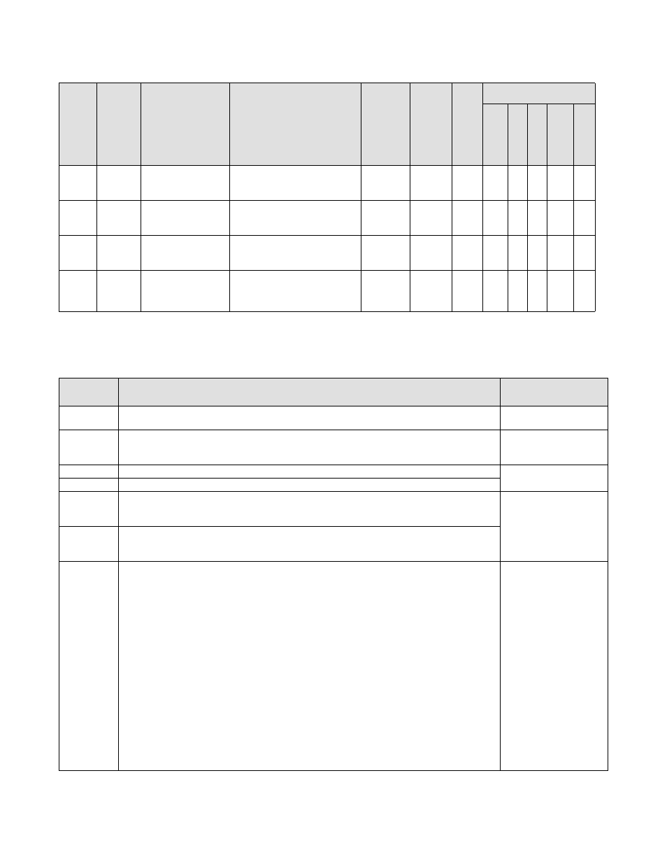
4.2
Modified Existing Parameters
Pa
ra
meter
Number
M
o
db
us
Ad
dr
es
s
Parameter
Name
Description
Rang
e
Default
Ch
an
ge
During Run
Control Mode
V/f
V/f w/ PG
O.
L.
V.
Flu
x
Ve
cto
r
O.L.V
. 2
C1-01
~
C1-08
200h
~
207h
Accel Time 1
~
Decel Time 8
Acceleration and Deceleration
Times
0.0 ~
6000.0
Sec.
2.0
Y
-
-
-
A
-
C2-01
~
C2-03
20bh
~
20dh
S-Crv @ Acc Start
S-Crv @ Acc End
S-Crv @ Dec Start
S-curve Times
0.00 ~
2.50
Sec.
0.00
N
-
-
-
A
-
d1-09
~
d1-16
280h
~
291h
Frequency Ref. 9
~
Frequency Ref. 16
Digital Preset Speeds
0.00 ~
400.00
Hz
6.09
~
6.16
Y
-
-
-
A
-
L3-04
492h
Stall Prevention
During Decel
0: Disabled
1: General Purpose
2: Intelligent
0 ~ 2
0
N
-
-
-
A
-
4.3
Modbus Registers
Modbus
Address
Description
Scaling
061Ch
Modbus Communication Speed Reference during a Move. Effective only when P1-02 = 2.
0.01 Hz
100 = 1.00 Hz
061Dh
Modbus Communication Position Reference (Engineering Units)
Actual position reference in encoder counts = 61Dh * P1-09.
Range is: 0.00 ~ 655.35 units. Effective only when P1-02 = 2.
0.01 Units
100 = 1.00 Units
061Ch
Modbus 32-bit Communication Position Reference (low word). Effective only when P1-02 = 3.
Quadrature
Encoder Counts
061Dh
Modbus 32-bit Communication Position Reference (high word). Effective only when P1-02 = 3.
0734h
32 Bit Distance From Home (low word)
Distance from home (+ home offset) for absolute applications, or distance from start of previous
move for relative applications. Read only.
Quadrature
Encoder Counts
0735h
32 Bit Distance From Home (high word)
Distance from home (+ home offset) for absolute applications, or distance from start of previous
move for relative applications. Read only.
0736h
Motion Control Modbus Status Register
Bits 0 ~ 5 are a copy of the information in monitor U1-11. Bits 6 ~ C behave the same as the
motion control digital outputs (H2-0X = 40 ~ 46). Read only.
Bit 0: Digital Output Status – M1-M2
Bit 1: Digital Output Status – M3-M4
Bit 2: Digital Output Status – M5-M6
Bit 3: Digital Output Status – P3-C3
Bit 4: Digital Output Status – P4-C4
Bit 5: Not Used
Bit 6: Not Used
Bit 7: Digital Output Status – MA-MB-MC (fault)
Bit 8: Move In Progress
Bit 9: Move Complete
Bit A: Homing Complete
Bit B: Homing Needed
Bit C: At Home
Bit D: Learn Successful
Bit E: Pre-Action Output
Bit F: Not Used
(N/A)