Yaskawa Motion Control G7 Drive Software User Manual
Page 15
Date: 05/16/08, Rev: 08-05
Page 15 of 38
TM.G7SW.117
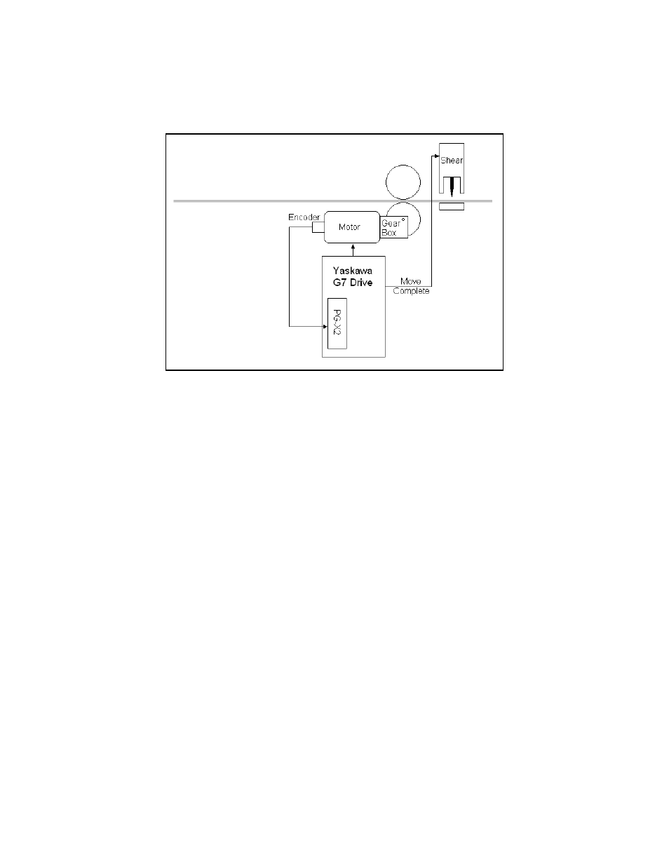
RELATIVE MOTION: Relative motion is used in applications such as cut-to-length and metering pumps. This type
of motion can be used with or without a homing sequence. When the motion type is “Relative Mem Off”
(P1-01 = 3), the move distance is measured from the position at the time of the move command. When the motion
type is “Relative Mem On” (P1-01 = 4), the distance is measured from the destination of the previous move. If a
conveyor with pockets or “flights” is being indexed, “Relative Mem On” is the appropriate motion type.
Figure 3: Relative Motion Example – Cut To Length
5.2
Commanded Position:
DIGITAL PRESET: Up to 16 different digital preset positions can be programmed. Each position is set in user
selectable units, set up by parameters P1-09 and P1-10. Distance in encoder counts can be calculated by
multiplying the digital preset value by parameter P1-09 (counts per rev). Encoder counts refer to the counts after
quadrature. The counts after quadrature are four times that of the “Pulses Per Revolution” rating of all compatible
encoders except the absolute gray code type. For the gray code type, encoder counts are NOT multiplied by 4.
Move velocity is determined by a different parameter for each digital preset position. Accel and Decel rates will be
one of 4 different sets as shown in Table 1 on the next page.
MODBUS DISTANCE: One 16 bit modbus register is used to command a speed during a move, and one 16 bit
modbus register is used to command a position. Modbus register 061Ch holds the speed reference (in 0.01 Hz),
and register 061Dh holds the position reference in engineering units (061Dh * P1-09). These registers can be
written by using the drive’s built-in modbus communications, or by other optional protocols such as DeviceNet,
Ethernet, Profibus or Modbus Plus. Accel and Decel rates are determined by parameters C1-01 and C1-02.
HIGH SPEED OPTION CARD REGISTER (Frequency Reference): In this mode, the option card’s frequency
reference is redefined and used as the commanded distance. The commanded position originates from the
“Frequency Reference” channel of the option card. The position reference is scaled as follows: Commanded
Position (in encoder counts) = Frequency Reference * P1-09. Move velocity is determined by parameter d1-09 and
Accel and Decel rates are determined by parameters C1-01 and C1-02.
For example: If P1-09 = 4096 counts / unit, and the frequency reference over the option PCB is 15.00 Hz, the result
is a move that is exactly 61,440 encoder counts (4096 * 15.00 = 61,440). When motion control is disabled, the
high-speed frequency reference channel returns to normal operation as an actual frequency reference.