Yaskawa AC Drive-Option BRAKING UNIT-CDBR Spec.D User Manual
Page 57
7 Setting and Confirming CDBR Braking Unit Operation
YASKAWA ELECTRIC TOBP C720600 01C 1000-Series Option CDBR-D, LKEB- Installation Manual
57
■
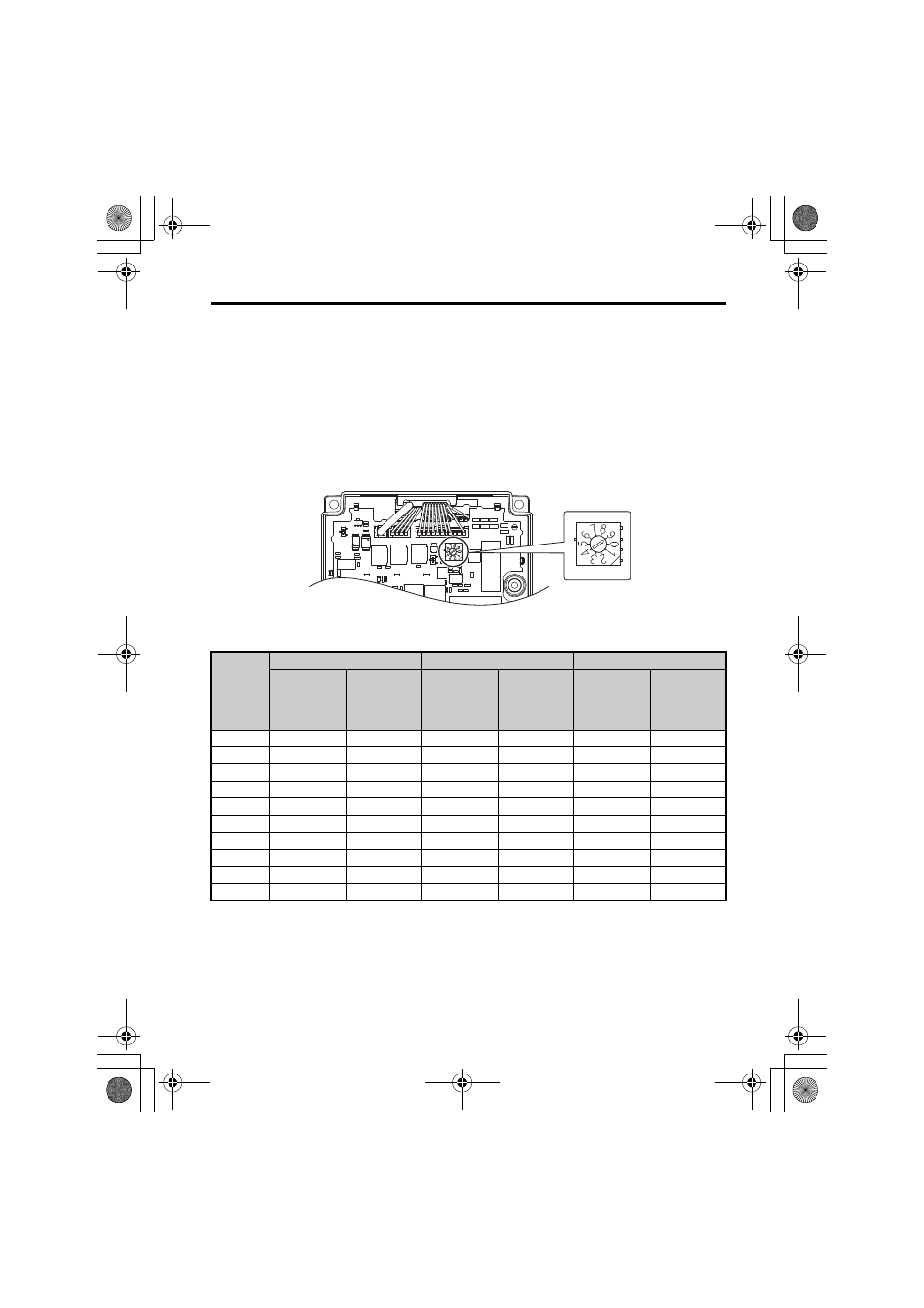
CDBR Braking Start Voltage Rotary Switch (S3)
Set the braking start level voltage level rotary switch S3 to match the power supply of the
main circuit. The default rotary switch S3 setting is 9. Refer to
switch S3 position and braking start voltage.
Note: 1. The setting does not typically require adjustment.
2. Consider the amount of voltage fluctuation in the DC bus when changing rotary switch S3 setting
values. If the starting voltage is incorrectly set to a low value, applying power to the drive may active
the CDBR and overheat the braking resistor.
3. Be sure to firmly click the switch into the proper position in accordance with the incoming power
supply. A switch that is stuck in between positions may cause the CDBR to operate incorrectly.
Figure 26
Figure 27 CDBR Voltage Activation Level, Rotary Switch (S3)
Table 14 Rotary Switch S3 Settings and Voltage Activation Levels
No.
<1> Default Setting
200 V Class
400 V Class
600 V Class
Input
Voltage
(V)
Braking
Activation
Voltage (V)
(PN Bus
Voltage)
Input
Voltage
(V)
Braking
Activation
Voltage (V)
(PN Bus
Voltage)
Input
Voltage
(V)
Braking
Activation
Voltage (V)
(PN Bus
Voltage)
0
160
270 (TYP)
380
630 (TYP)
500
825 (TYP)
1
170
282 (TYP)
390
644 (TYP)
505
839 (TYP)
2
175
294 (TYP)
400
659 (TYP)
515
853 (TYP)
3
185
307 (TYP)
405
673 (TYP)
525
867 (TYP)
4
190
319 (TYP)
415
688 (TYP)
530
881 (TYP)
5
200
331 (TYP)
425
702 (TYP)
540
894 (TYP)
6
208
343 (TYP)
430
717 (TYP)
550
908 (TYP)
7
215
356 (TYP)
440
731 (TYP)
555
922 (TYP)
8
220
368 (TYP)
450
746 (TYP)
565
936 (TYP)
230
380 (TYP)
460
760 (TYP)
575
950 (TYP)
Default: 9
TOBP_C720600_01C_3_0_E.fm 57 ページ 2013年10月7日 月曜日 午後2時20分