Yaskawa AC Drive-Option BRAKING UNIT-CDBR Spec.D User Manual
Page 52
6 Electrical Installation
52
YASKAWA ELECTRIC TOBP C720600 01C 1000-Series Option CDBR-D, LKEB- Installation Manual
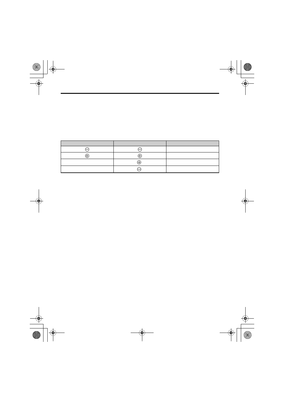
Replacing Previous Version CDBR Braking Unit Models
The terminal size and location are different from the ones on the older models of the CDBR
braking units (CDBR-, CDBR-B, CDBR-C).
Refer to
when replacing an older model CDBR Braking Units to ensure proper
wiring.
Table 12 Main Circuit Terminal Cross-Reference Chart
for New and Previous Version Model CDBR Braking Units
■
Using CDBR Braking Units in Parallel
Be sure to install multiple CDBR Braking Units in a master/slave configuration with a single
CDBR Braking Unit as the master.
illustrates how to wire CDBR Braking Units
in parallel.
NOTICE: Perform all wiring and installation as instructed below. Failure to follow specifications may damage
the drive and the CDBR braking unit.
• Set the Master/Slave Selection Switch (S2) to “Master (OUT)” on one CDBR Braking
Unit only. Set all other CDBR Braking Units to Slave (IN). Refer to
Selection Switch (S2) on page 56
• Follow wire specifications when connecting the CDBR Braking Unit. Refer to
for details.
• Use shielded twisted-pair cables and keep the wiring distance between the OUT1-IN1 and
OUT2-IN2 terminals of the CDBR Braking Unit shorter than 1 meter.
CDBR-D
CDBR-B, CDBR-C
CDBR-
N
P
B1
0
P
0
B2
0
B
TOBP_C720600_01C_3_0_E.fm 52 ページ 2013年10月7日 月曜日 午後2時20分