Master/slave, For details – Yaskawa AC Drive-Option BRAKING UNIT-CDBR Spec.D User Manual
Page 56
7 Setting and Confirming CDBR Braking Unit Operation
56
YASKAWA ELECTRIC TOBP C720600 01C 1000-Series Option CDBR-D, LKEB- Installation Manual
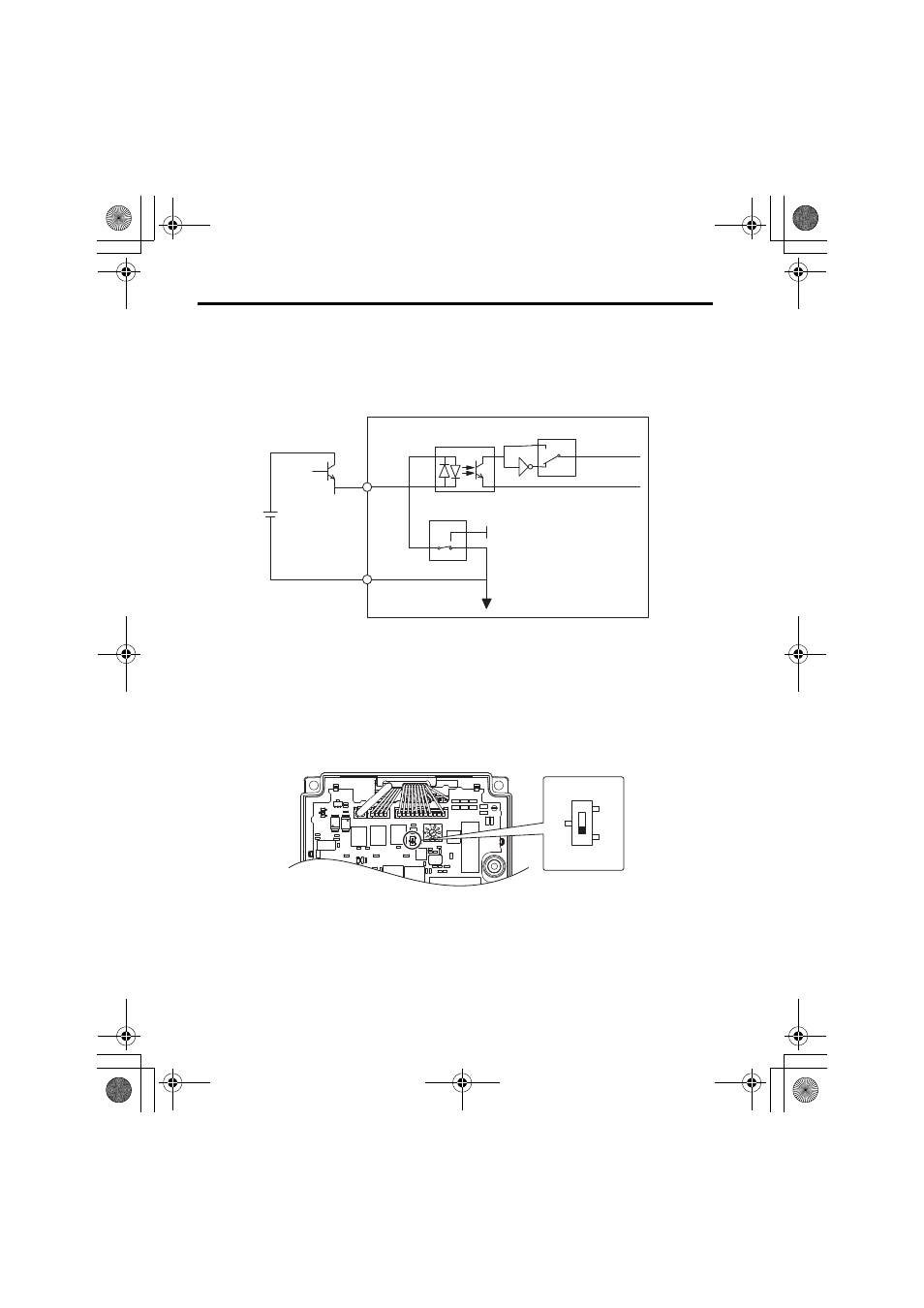
Source Mode (+24 V Common), Internal Power Supply
When controlling digital inputs by PNP transistors (+24 V common/sourcing mode) or
contact inputs using the drive internal power supply, set DIP switch S1 for sourcing as
shown in
.
Figure 24
Figure 25 CDBR Braking Unit Sourcing Mode
■
Master/Slave Selection Switch (S2)
The default setting of DIP switch S2 is OUT (Master). Change the switch position only
when operating the unit as a slave device.
Only the properly configured master CDBR should have DIP switch S2 set to OUT (master).
All other units in the circuit must have DIP switch S2 set to IN (slave). Refer to
CDBR Braking Units in Parallel on page 52
for details.
Figure 25
Figure 26 Master/Slave Selection Switch (S2)
+24 V
SINK-default
SOURCE
SB
SC
S1
S4
A (N.O.(default))
B (N.C.)
24 V External
Power Supply
(24 Vdc, 5 mA)
IN (Slave)
OUT (Master)
TOBP_C720600_01C_3_0_E.fm 56 ページ 2013年10月7日 月曜日 午後2時20分
- Tag Generator (30 pages)
- MP3300iec (82 pages)
- 1000 Hz High Frequency (18 pages)
- 1000 Series (7 pages)
- PS-A10LB (39 pages)
- iQpump Micro User Manual (300 pages)
- 1000 Series Drive Option - Digital Input (30 pages)
- 1000 Series Drive Option - CANopen (39 pages)
- 1000 Series Drive Option - Analog Monitor (27 pages)
- 1000 Series Drive Option - CANopen Technical Manual (37 pages)
- 1000 Series Drive Option - CC-Link (38 pages)
- 1000 Series Drive Option - CC-Link Technical Manual (36 pages)
- 1000 Series Drive Option - DeviceNet (37 pages)
- 1000 Series Drive Option - DeviceNet Technical Manual (81 pages)
- 1000 Series Drive Option - MECHATROLINK-II (32 pages)
- 1000 Series Drive Option - Digital Output (31 pages)
- 1000 Series Drive Option - MECHATROLINK-II Technical Manual (41 pages)
- 1000 Series Drive Option - Profibus-DP (35 pages)
- AC Drive 1000-Series Option PG-RT3 Motor (36 pages)
- Z1000U HVAC MATRIX Drive Quick Start (378 pages)
- 1000 Series Operator Mounting Kit NEMA Type 4X (20 pages)
- 1000 Series Drive Option - Profibus-DP Technical Manual (44 pages)
- CopyUnitManager (38 pages)
- 1000 Series Option - JVOP-182 Remote LED (58 pages)
- 1000 Series Option - PG-X3 Line Driver (31 pages)
- SI-EN3 Technical Manual (68 pages)
- JVOP-181 (22 pages)
- JVOP-181 USB Copy Unit (2 pages)
- SI-EN3 (54 pages)
- SI-ET3 (49 pages)
- MECHATROLINK-III (35 pages)
- EtherNet/IP (50 pages)
- SI-EM3 (51 pages)
- 1000-Series Option PG-E3 Motor Encoder Feedback (33 pages)
- 1000-Series Option SI-EP3 PROFINET (56 pages)
- PROFINET (62 pages)
- AC Drive 1000-Series Option PG-RT3 Motor (45 pages)
- SI-EP3 PROFINET Technical Manual (53 pages)
- A1000 Drive Option - BACnet MS/TP (48 pages)
- 120 Series I/O Modules (308 pages)
- A1000 12-Pulse (92 pages)
- A1000 Drive Software Technical Manual (16 pages)
- A1000 Quick Start (2 pages)
- JUNMA Series AC SERVOMOTOR (1 page)
- A1000 Option DI-101 120 Vac Digital Input Option (24 pages)