Table 10, 6 electrical installation – Yaskawa AC Drive-Option BRAKING UNIT-CDBR Spec.D User Manual
Page 50
6 Electrical Installation
50
YASKAWA ELECTRIC TOBP C720600 01C 1000-Series Option CDBR-D, LKEB- Installation Manual
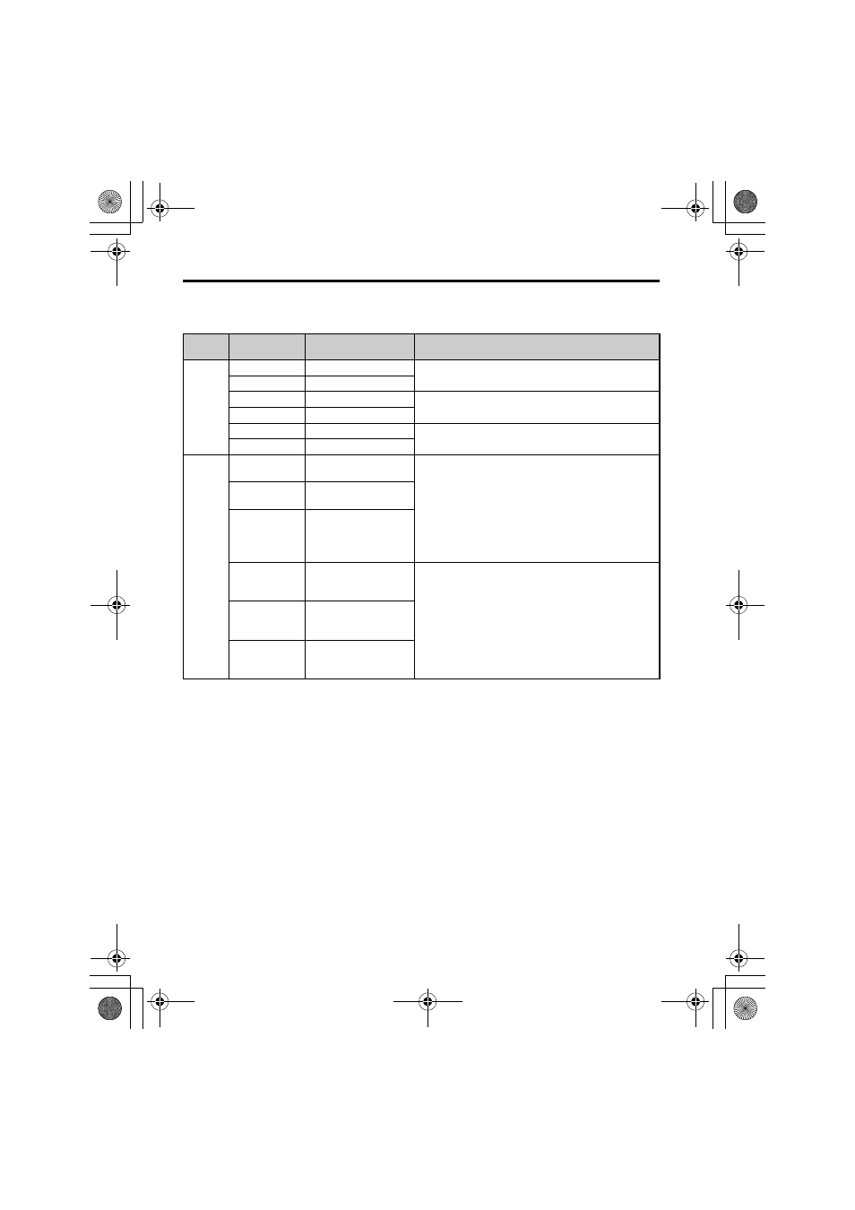
Table 10 CDBR Braking Unit Control Circuit Terminals
Terminal
Block
<1> Digital Input-SB, SC. Powered by internal 24 Vdc LVLC source. If external power supply used, it shall be UL
Listed Class 2 power source only or equivalent.
Terminal No.
Terminal Name
Specification
TB1
IN1
Slave Input
Input the signal when using CDBR braking units in
parallel.
IN2
Slave Input Common
OUT1
Master Output
Output the signal when using CDBR braking units in
parallel.
OUT2
Master Output Common
SC
Enable Input Common
Enable/Disable contact input to disable the CDBR and
activate MA-MB-MC fault contact output.
SB
Enable Input
TB2
MA
Fault Contact Output
(N.O.)
Output signal when a fault occurs or when SB-SC is closed
(default) (example: CDBR braking unit overheating, LKEB
braking resistor unit short-circuit detection, external fault).
Wiring sequence should shut off power to the drive when
the signal is output.
Relay output
250 Vac, max.1 A
30 Vdc, max.1 A
min.5 Vdc, 10 mA
MB
Fault Contact Output
(N.C.)
MC
Fault Contact Output
Common
EA
CDBR Transistor
Short-Circuit Detection
Output (N.O.)
Output signal when braking unit fault is detected.
If needed, wiring sequence should shut off power to the
drive when the signal is output.
Relay output
250 Vac, max.1 A
30 Vdc, max.1 A
min.5 Vdc, 10 mA
EB
CDBR Transistor
Short-Circuit Detection
Output (N.C.)
EC
CDBR Transistor
Short-Circuit Detection
Output Common
TOBP_C720600_01C_3_0_E.fm 50 ページ 2013年11月1日 金曜日 午後2時49分