Programming the pac blocks – Yaskawa Modicon 800 Series Remote I/O Network for use on Microtrac LAN User Manual
Page 13
3
SOFTWARE
12
Programming the PAC Blocks
5/24/96
The PLC gateway receives messages from the MicroTrac LAN. Each of these
messages contains a channel number. This channel number specifies which
Modicon module the message is addressing. The channel number can range
from 011 to 249.
CAUTION
Drop 9 Slot 9 cannot be used, since it corresponds to MicroTrac
channel 99, which is reserved for other functions.
The least significant digit is used to specify the slot number, and the two most
significant digits specify the drop number. The rack is always assumed to be
two (2). When dealing with analog data, there is always a sub-channel field
that specifies the word within the analog module the message is addressing.
This can range from 1 to 8. The discrete messages have a mask field which
specifies the bits the message is addressing.
EXAMPLE
An example may help clarify the above. Let’s assume we want the drives to
input discrete data from the Modicon PLC and output one word of analog data
to the PLC. Drop 2 is not used by a real drop, so we can choose that as our
simulated drop. In the Modicon Traffic Cop for drop 2, rack 2, slot 1, we enter
a B804 discrete output module. In slot 2 of the same rack we enter a B865
register input module. There is no special reason for choosing drop 2 or slots
1 & 2.
The PAC program is responsible for supplying the PLC with information about
where the simulated modules are located. After power-up, each node on the
MicroTrac LAN that wants to read/write data to the Modicon PLC will send
messages to the gateway indicating which modules it needs to communicate
with.
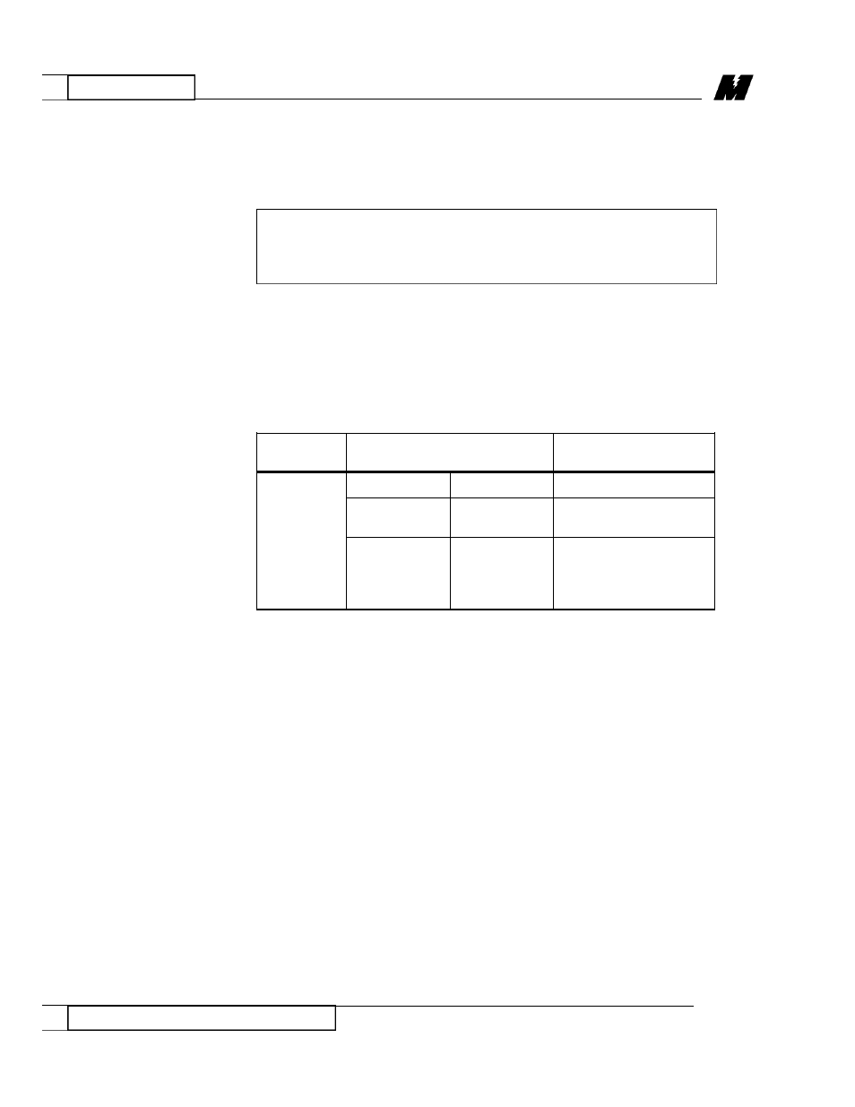
Programming
the PAC Blocks
LAN Node
LAN Channel
LAN Sub-Channel
Number
Number
NUMBER
200 -
XX
X
- XX
Modicon
Modicon
Modicon Bit No.
Drop No.
Slot No.
Range =
Range =
Range = 01 to 16
01 to 24
01 to 09
for logics
Range = 01 to 08
for numerics
RD 3004-20