Gpd506/p5, Product transition guide terminal comparison – Yaskawa GPD506/P5 to P7 User Manual
Page 16
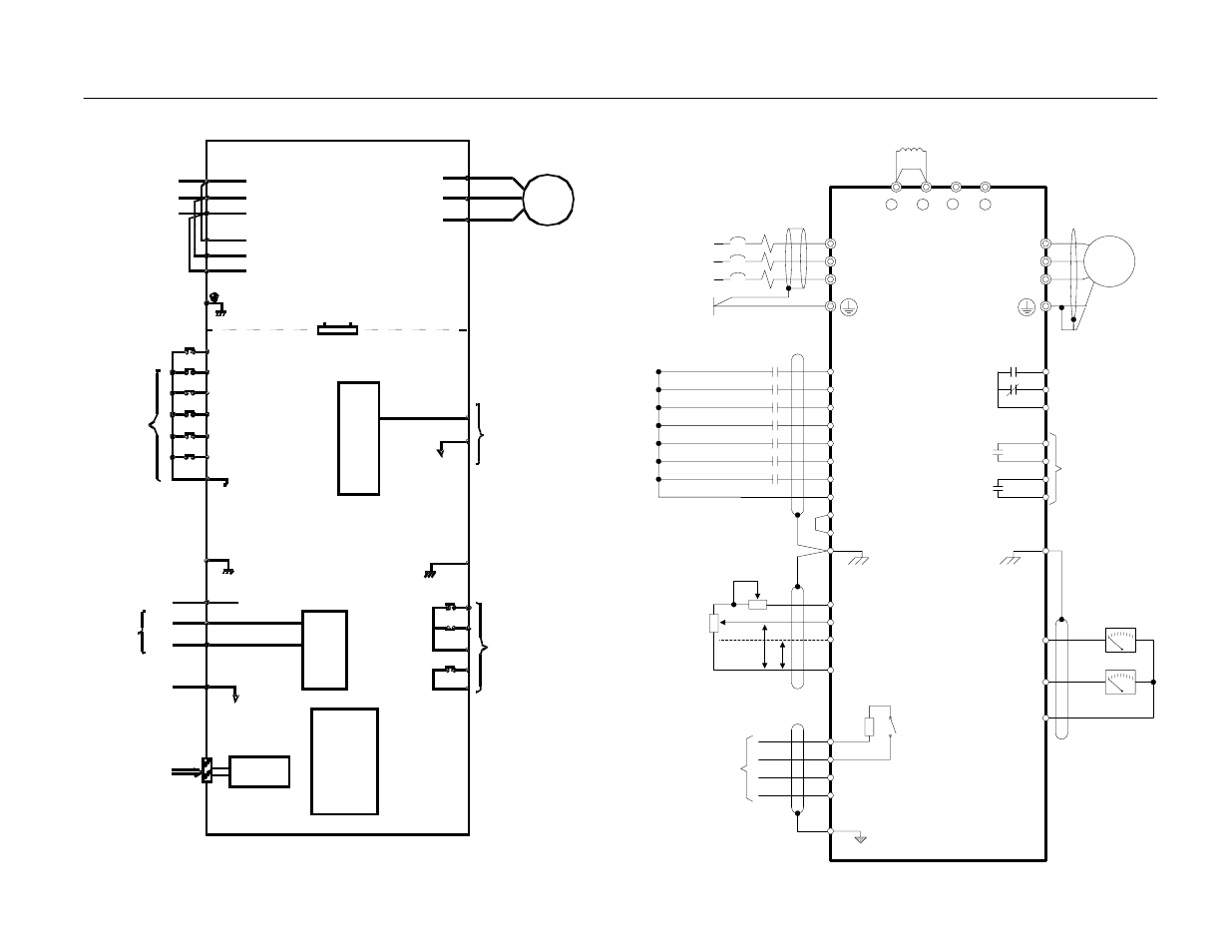
Product Transition Guide
Terminal Comparison
Page
16
of 48
T/L3
S/L2
R/L1
S3 (H1-01)
S2
S1
SC
E(G)
SP
S4 (H1-02)
S5 (H1-03)
S6 (H1-04)
S7 (H1-05)
SN
+V +15VDC, 20mA
A1 0-10VDC, 20 K
A2 (H3-08)
4-20mA, 250 K
[0 to +10VDC, 20K ]
AC
S+
R-
R+
S-
IG
1
+
2
+
3
+
-
E7
W/T3
V/T2
U/T1
MC
MB
MA
M2
M1
M4
M3
E(G)
(H4-01)
FM
(H4-04)
AM
AC
(H2-01)
(H2-02)
Modbus
RS-485/422
Ω
Ω
Ω
4 to 20mA
P
P
External
Frequency
Reference
2k
Ω
MCCB
L3
L2
L1
PE
3-Phase
Power Supply
50/60Hz
External Fault
Reverse Run/Stop
Foward Run/Stop
Fault Reset
Multi-step Speed Setting 1
Multi-step Speed Setting 2
Jog Frequency Reference
Multi-function
Contact Inputs
(Factory Default)
M
Motor
Fault Contact
Digital Output
250VAC/30VDC, 1A
Multi-function
Digital Outputs
250VAC/30VDC, 1A
Digital Output 1
(Default: During RUN)
Digital Output 2
(Default: Remote/
Auto Operation)
+
-
+
-
Multi-function
Analog Outputs
0 to +10VDC, 2mA
S1-1
2k
Shorting Bar Standard:
CIMR-P7U23P7 to 2018
CIMR-P7U43P7 to 4018
DC Reactor Standard:
CIMR-P7U2022 to 2110
CIMR-P7U4030 to 4300
U
X
11
0
Terminating
Resistance
P7
Digital
RS-232
Serial Port
Analog Inputs
(250
Ω
)
Operator
Input FI selectable
4~20mA
or
0~10V
(10-pin)
S1 - Fixed
S2
S3
SC (Com)
S4
S5
S6
FS
FV
FI
FC
PWM
8
bit
Multi-Function
Inputs
G
(+15V)
(20k
Ω
)
(0V)
0~
+
10V
4~20mA
0~10V
AM
(Com) AC
G
MA
MB
MC
M1
M2
Multi-Function
Analog Outputs
Multi-Function
Relay Outputs
A/D
10 bit
IM
L11
L21
L31
L1
L2
L3
T1
T2
T3
Gate Drive
GPD506/P5