4 connecting rs485 to the sunny webbox – SMA Off-Grid Systems User Manual
Page 29
SMA Solar Technology AG
5 Single-Cluster System
Installation - Quick Reference Guide
Off-Grid-IS-en-30
29
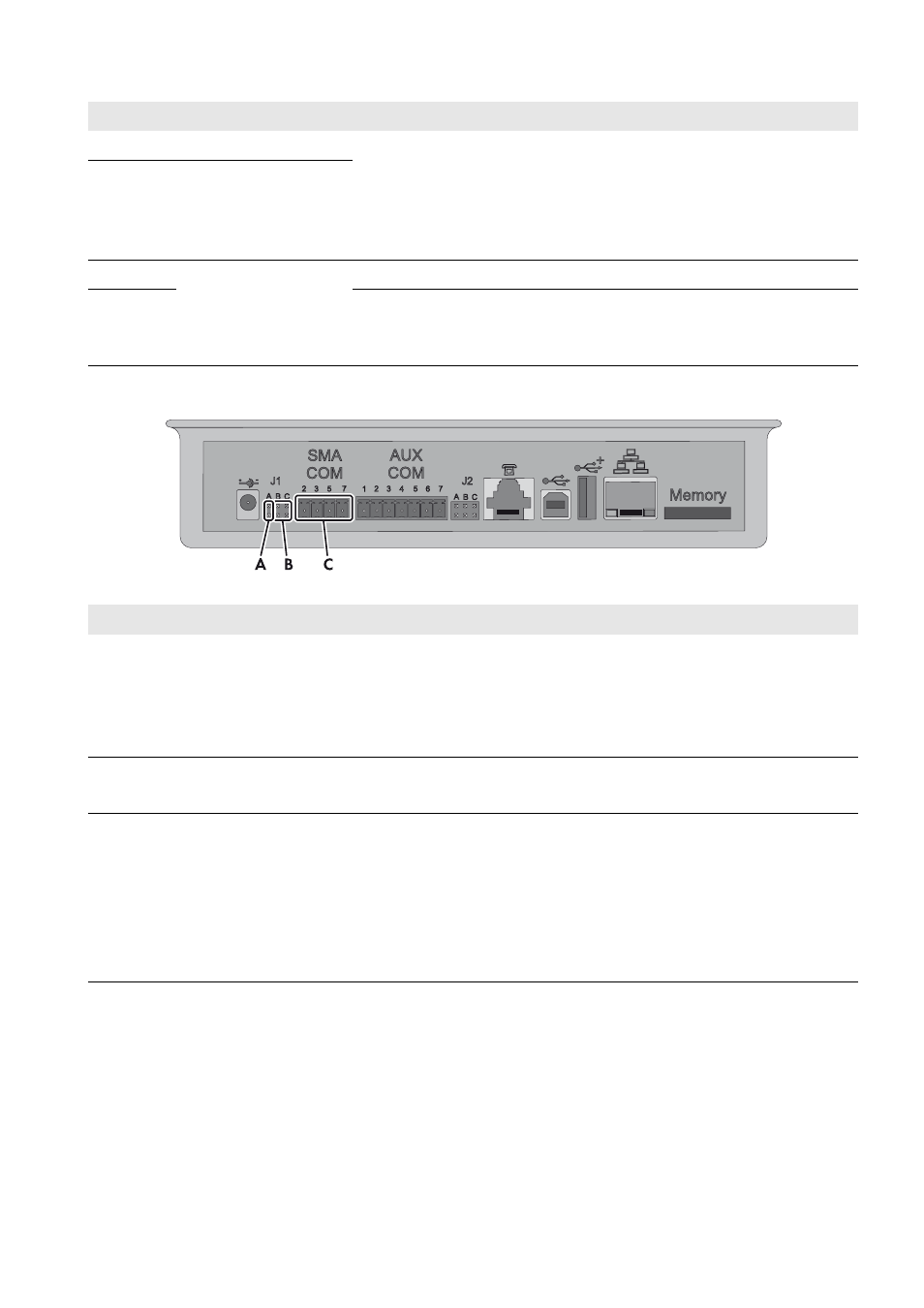
5.4 Connecting RS485 to the Sunny WebBox
Figure 12: Connecting the RS485 communication bus to the Sunny WebBox
C
DC+ cable
Battery terminal
For a single-phase system, the cable length and the conductor cross-section
must be identical on each Sunny Island.
Conductor cross-section: 50 mm² to 95 mm²
Cable diameter: 14 mm to 25 mm
D
DC − cable
E
Data cable for the
internal communication in
the cluster
Sunny Island: terminal ComSync In
F
Sunny Island: terminal ComSync Out
On slave 2 either connect the data cable of the Sunny Island Charger charge
controller or insert the terminator into the terminal.
Position
Designation
Description/information
A
Jumper J1A
Terminator
If the Sunny WebBox is installed at the end of the communication bus,
a jumper must be inserted.
If the Sunny WebBox is installed between two nodes, the jumper must be
removed.
B
Jumper J1B and J1C
Signal bias voltage
Make sure that both jumpers are inserted.
C
SMACOM
Terminal RS485
2: Signal Data+ (A), color coding of the insulated conductor:
green with white stripes
5: Signal GND, color coding of the insulated conductor:
orange with white stripes
7: Signal Data − (B), color coding of the insulated conductor:
white with green stripes
Position
Designation
Description/information