SMA SC 500CP XT Installation User Manual
Page 31
Procedure:
1. Disassemble the panels (see Section 7.2.1, page 40).
2. Insert the optical fibers in the inverter (see Section 7.1, page 40).
3. Remove the splice box from the top-hat rail:
4. Open the enclosure of the splice box.
5. Insert the optical fibers from below through the cable gland into the splice box.
6. Mount the subscriber connectors on the optical fibers.
7. Plug the subscriber connectors into the SC-P plugs in the splice box.
8. Coil the residual glass fiber in the fiber reservoir. Observe the permissible bend radii.
9. Screw on the enclosure of the splice box.
10. Reinstall the splice box on the top-hat rail.
11. Attach the optical fibers to the cable support rail using a cable tie. This ensures that the optical fibers cannot be
pulled out inadvertently.
12. Mount the panels (see Section 7.2.1, page 40).
5.6.2
Connecting Optical Fibers via Optical Fiber Pigtail
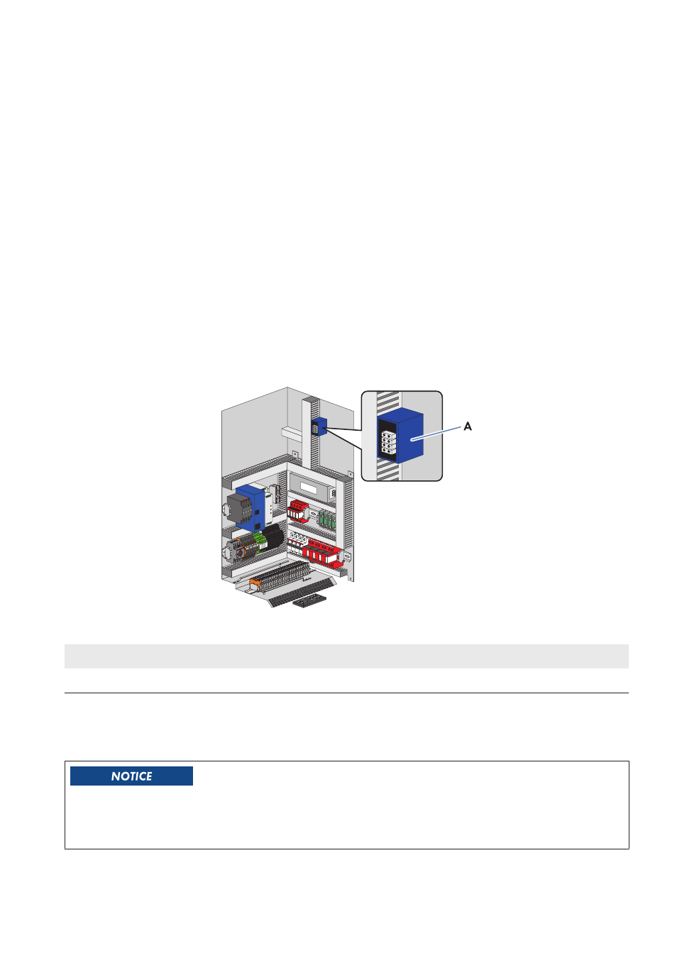
Figure 11: Position of the splice box
Position
Designation
A
Splice box
Optical fiber requirements:
☐ The optical fiber cables must be equipped with a 50 μm multi-mode optical fiber.
☐ The optical fibers must be fitted with a subscriber connector.
Damage to optical fibers due to too tight bend radii
Excessive bending or kinking will damage the optical fibers.
• Observe the minimum permissible bend radii of the optical fibers.
5 Installation
SMA Solar Technology AG
Operating Manual
31
SCCPXT-IA-E4-en-44