3 connecting additional grounding, 4 dc connection, 1 requirements for the dc connection – SMA SB 3000TL User Manual
Page 27: Connecting additional grounding, Dc connection, Requirements for the dc connection
6.3.3
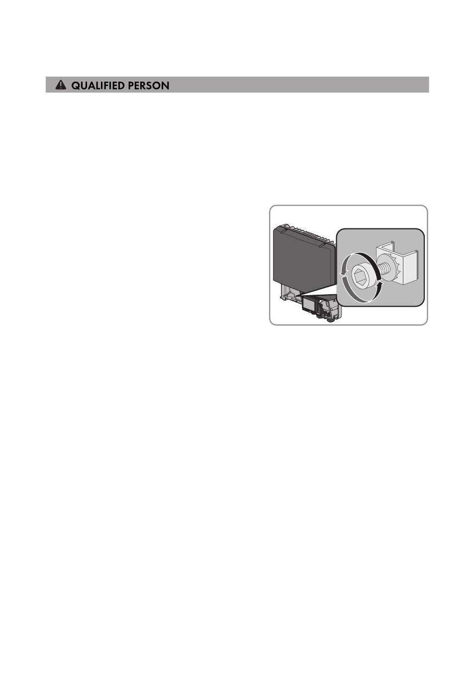
Connecting Additional Grounding
If additional grounding or equipotential bonding is required locally, you can connect additional
grounding to the inverter. This prevents touch current if the grounding conductor at the terminal for
the AC cable fails.
Cable requirement:
☐ Grounding cable cross-section: max. 10 mm²
Procedure:
1. Strip the grounding cable insulation.
2. Release the screw using an Allen key (AF 4) until
the grounding cable can be led under the
clamping bracket.
3. Feed the grounding cable under the clamping bracket. Position the grounding conductor on
the left-hand side.
4. Tighten the clamping bracket with the screw and conical spring washer (torque: 6 Nm). The
teeth of the conical spring washer must face the clamping bracket.
6.4
DC Connection
6.4.1
Requirements for the DC Connection
Requirements for the PV modules per input:
☐ All PV modules must be of the same type.
☐ All PV modules must be aligned and tilted identically.
☐ On the coldest day based on statistical records, the open-circuit voltage of the PV array must
never exceed the maximum input voltage of the inverter.
☐ The same number of series-connected PV modules must be connected to each string.
☐ The maximum input current per string must be maintained and must not exceed the through-
fault current of the DC connectors (see Section 11 "Technical Data", page 47).
☐ The thresholds for the input voltage and the input current of the inverter must be adhered to
(see Section 11 "Technical Data", page 47).
6 Electrical Connection
SMA Solar Technology AG
Operating Manual
27
SB30-50TL-21-BE-en-11