2 overview of the connection area, 1 view from below, Overview of the connection area – SMA SB 3000TL User Manual
Page 22: View from below
6.2
Overview of the Connection Area
6.2.1
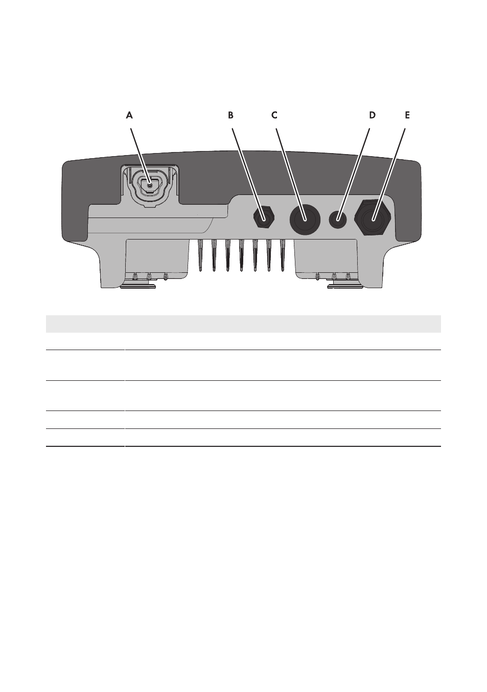
View from Below
Figure 6: Enclosure openings at the bottom of the inverter
Position
Designation
A
Pin connector for the ESS*
B
Cable gland M20x1.5 for the connection to the multifunction relay or
SMA Power Control Module*
C
Enclosure opening with filler plug for cable gland M32x1.5 with two-hole ca-
ble support sleeve
D
Enclosure opening with filler plug
E
Cable gland M32x1.5 for the AC cable
* Optional
6 Electrical Connection
SMA Solar Technology AG
Operating Manual
SB30-50TL-21-BE-en-11
22