2 interior view, Interior view – SMA SB 3000TL User Manual
Page 23
6.2.2
Interior View
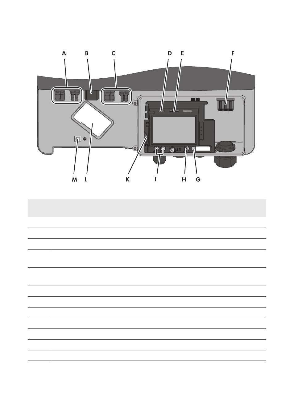
Figure 7: Connection areas in the interior of the inverter
Posi-
tion
Designation
A
2 positive and 2 negative DC connectors, input A
B
Pin connector for the ESS*
C
2 positive and 2 negative DC connectors, input B
D
Pin connector for connecting the multifunction relay, the SMA Power Control Module or
the fan retrofit kit*
E
Pin connector for connecting the Speedwire/Webconnect interface or the RS485 inter-
face*
F
Connecting terminal plate for connecting the AC cable
G
Switch for temporarily changing the display language to English (for service purposes)
H
Rotary switch C for configuring the NetID
I
Rotary switch A and B for setting the country data set and the display language
K
Slot for SD memory card
L
Mounting location for the fan retrofit kit*
M
Grounding terminal for additional grounding of the inverter
* Optional
6 Electrical Connection
SMA Solar Technology AG
Operating Manual
23
SB30-50TL-21-BE-en-11