SMA 20000TL User Manual
Page 34
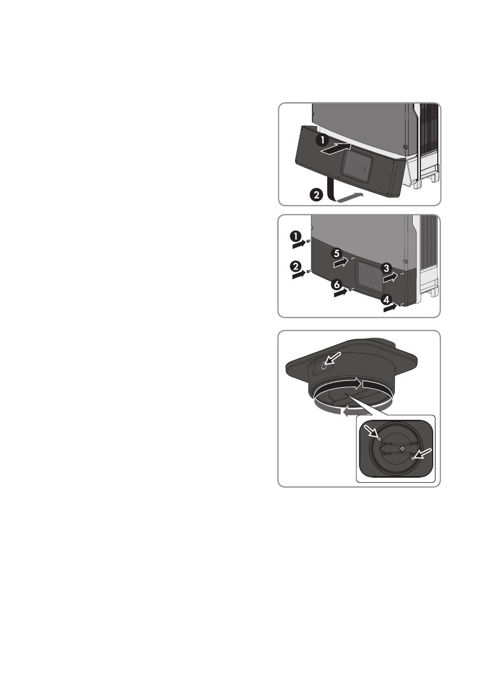
Procedure:
1. Make sure that the AC cable is routed so that it cannot be damaged by the partition in the
lower enclosure lid.
2. Insert the lower enclosure lid from above and
flip it down. The screws must protrude from the
lower enclosure lid.
3. Tighten all six screws with an Allen key (AF 3) in
the order 1 to 6 (torque: 2.0 Nm ± 0.3 Nm). By
tightening the screws in the prescribed order,
you avoid warping the enclosure lid, which
would keep it from sealing correctly.
Useful hint: If the screws fall out of the lower
enclosure lid, insert the long screw into the lower
middle hole and the five short screws into the
other holes.
4. Set the DC load-break switch to position O so
that both mounting screws are visible.
5. Insert the DC load-break switch firmly into the recess on the inverter. During this process, the
DC load-break switch must still be in position O and aligned so that the screws are positioned
over the threads.
7 Commissioning
SMA Solar Technology AG
Operating Manual
STP20-25TL-BE-en-12
34