2 mounting the inverter, Mounting the inverter – SMA 20000TL User Manual
Page 18
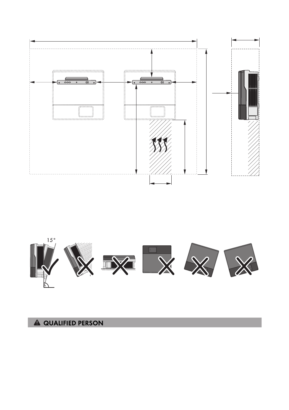
1382
mm
2224 mm
530 mm
50 mm
400
mm
190 mm
315 mm
415 mm
438
mm
415 mm
940
mm
Figure 4: Recommended clearances
Permitted and prohibited mounting positions:
☐ The inverter must only be mounted in one of the permitted positions. This will ensure that no
moisture can penetrate the inverter.
☐ The inverter should be mounted in such a way that LED signals can be read without difficulty.
Figure 5: Permitted and prohibited mounting positions:
5.2
Mounting the Inverter
Additionally required mounting material (not included in the scope of delivery):
☐ At least two screws suitable for the support surface (diameter: 10 mm at maximum)
☐ At least two washers that are suitable for the screws (diameter: 30 mm at maximum)
☐ If necessary, two screw anchors suitable for the support surface and the screws
5 Mounting
SMA Solar Technology AG
Operating Manual
STP20-25TL-BE-en-12
18