Pwm 20 in – HEIDENHAIN PWM 20 User Manual
Page 133

134
HEIDENHAIN PWM 20 Testing Package – Cable and Connection Technology
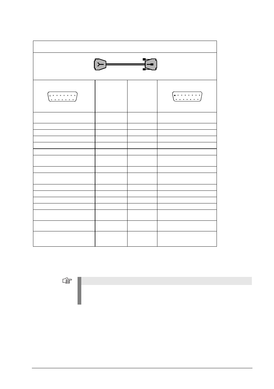
4.3.70 Connecting cable for LIP 2xx compensation 15/15-pin D-sub (1 Vpp) PWM 20 X1 IN
Note
This is the assignment for adjusting LIP 2xx (three additional pins are assigned)! Do not start
the adjustment, if the PWM 20 is in feed-through mode.
Danger of uncontrolled machine motions!
1
9
2
10
3
5
4
6
8
7
11 12 13 14 15
8
15
7
14
6
4
5
3
1
2
13 12 11 10 9
PWM 20 IN
Verbindungskabel ID 735541-xx
Connecting cable ID 735541-xx
Signal 1 Vss
Signal 1 Vpp
Farbe
Color
Sub-D-Stecker 15-pol. Buchse
15-pin D-sub connector (female)
Sub-D-Stecker
15-pol.
Stift
15-pin D-sub connector (male)
PIN 7
R-
schwarz / black
PIN 7
PIN 9
A-
grün / green
PIN 9
PIN 10
0 V Sensor
weiß / white
PIN 10
PIN 12
+V Sensor
blau / blue
PIN 12
PIN 3
B+
grau / grey
PIN 3
PIN 4
+V
U
P
braun/grün
brown/green
PIN 4
PIN 14
R+
rot / red
PIN 14
PIN 2
0 V
U
N
weiß/grün
white/green
PIN 2
PIN 11
B-
rosa / pink
PIN 11
PIN 1
A+
braun / brown
PIN 1
PIN 13
CLOCK
violett / violet
PIN 13
PIN 15
DATA
gelb / yellow
PIN 15
PIN 5
Selbsttestsignal
self-test signal
rot/schwarz
red/black
PIN 5
Gehäuse
Housing
Außenschirm
External shield
Schirm /
Shield
Gehäuse
Housing
PIN 6, 8
frei / free
nicht belegt / not used
PIN 6, 8
frei / free
nicht belegt / not used
