Operation – HEIDENHAIN ND 1400 Quick Start User Manual
Page 5
3
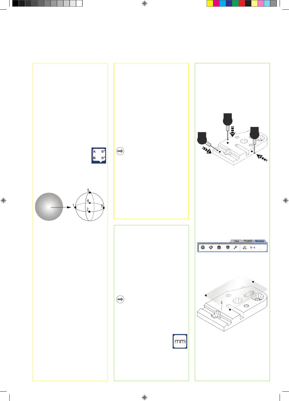
Probing points
When probing part features using a
touch probe:
• Approach the surface at 90 degrees.
• Approach the surface without
changing direction in the last 5 mm.
• Do not drag the probe across the
surface.
• Do not probe sharp edge transitions.
Leveling and aligning the part
Perform level and skew alignments to
eliminate measurement errors resulting
from misaligned parts.
1. Align the part on the stage
Align the reference edge of the part to a
measurement axis.
2. Level the part
• Touch the MEASURE tab to display
the 3D measure icons, and then touch
the PLANE icon.
• Probe a minimum of 3 points on the
desired part reference-plane surface
and then press the FINISH key.
• Touch the ALIGN and ZERO buttons
on the DRO screen to level the plane
at Z = 0.
11. Calibrate stage squareness
This calibration is not necessary when
NLEC error correction is used.
• Align the squareness calibration
artifact to the reference axis.
• Measure the artifact angle. Refer to
the angle measurement instructions
later in this document if necessary.
• Display the SETUP MENU and then
touch the SQUARENESS menu item.
• Enter the measured angle into the
OBSERVED ANGLE field and then
enter the certified artifact angle into
the STANDARD ANGLE field.
• Press the FINISH key to complete the
calibration.
Note:
Many more setup functions are available
beyond the minimum parameters
discussed here. Refer to the ND 1400
User Guide for detailed instructions.
Operation
7. Encoder setup
• Touch the ENCODERS setup menu
item and then touch the AXIS field to
select the desired encoder axis.
• Enter all the required encoder
parameters.
• Calibrate analog encoders by touching
the CAL button. TTL encoders do not
require calibration.
• Repeat setup for all axes.
8. Display formatting
• Touch the DISPLAY setup menu item.
• Enter the desired display resolutions
and other parameters.
9. Qualify the touch probe
• Touch the PROBE HOLDER
icon to display the probe
properties screen for the
selected probe.
• Touch the TEACH button to initiate
probe qualification.
• Probe 4 points around the sphere
circumference, and then 1 at the top.
• Press the FINISH button to conclude
the probe qualification.
10. Error correction
Linear (LEC), segmented linear (SLEC)
and nonlinear (NLEC) error correction
methods can be used to compensate
for encoder and machine errors.
Refer to the ND 1400 User Guide for
instructions.
Preparing to measure
1. Power up the ND 1400
• Check connections to the ND 1400.
• Press the POWER SWITCH to power
the ND 1400. The DRO screen will be
displayed after system initialization.
2. Find machine zero (optional)
Move the stage to cross reference
marks or find hard stops if your system
was set up to establish machine zero at
startup.
Note:
A repeatable machine zero is required
when SLEC or NLEC error correction
is used. Refer to the User’s Guide for
detailed information.
3. Select a unit of measure
Touch the UNIT OF MEASURE
icon to toggle between inches
and mm.