Pinouts, Main panel – Grass Valley Zodiak Installation Planning Guide User Manual
Page 36
36
Zodiak Installation Planning Guide
Pinouts
Pinouts
Main Panel
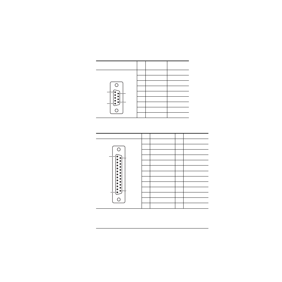
Table 9. Main Panel COM1 and COM2 Ports
Serial Ports
RS-232
Pin
Main Panel
Proc. Com 1
Main Panel
Proc. Com 2
1
DSD
DSD
2
TXD
TXD
3
RXD
RXD
4
DSR
DSR
5
Chassis GND
Chassis GND
6
DTR
DTR
7
CTS
CTS
8
RTS
RTS
9
Menu Reset
a
a
Reset is active low.
Reserved
Table 10. Main Panel GPI Inputs and Outputs
GPI Pin
Function
Pin
Function
1
Chassis GND
14
IN 1B
2
IN 1A
15
Chassis GND
3
IN 2A
16
IN 2B
4
Chassis GND
17
IN 3B
5
IN 3A
18
Chassis GND
6
IN 4A
19
IN 4B
7
Chassis GND
20
OUT 1B
8
OUT 1A
21
Chassis GND
9
OUT 2A
22
OUT 2B
10
Chassis GND
23
OUT 3B
11
OUT 3A
24
Chassis GND
12
OUT 4A
25
OUT 4B
13
Chassis GND
Notes:
Inputs are opto-isolated.
A and B are polarity independent.
Apply from 5 to 24 volts between A and B Inputs to turn on.
Outputs are normally open relay closures between A and B.
Pin 5
Pin 6
Pin 9
D-9 Female
Pin 1
Pin 1
Pin 13
Pin 14
Pin 25
D-25 Female
- LDK 5302 (24 pages)
- SFP Optical Converters (18 pages)
- 2000GEN (22 pages)
- 2011RDA (28 pages)
- 2010RDA-16 (28 pages)
- 2000NET v3.2.2 (72 pages)
- 2000NET v3.1 (68 pages)
- 2020DAC D-To-A (30 pages)
- 2000NET v4.0.0 (92 pages)
- 2020ADC A-To-D (32 pages)
- 2030RDA (36 pages)
- 2031RDA-SM (38 pages)
- 2041EDA (20 pages)
- 2040RDA (24 pages)
- 2041RDA (24 pages)
- 2042EDA (26 pages)
- 2090MDC (30 pages)
- 2040RDA-FR (52 pages)
- LDK 4021 (22 pages)
- 3DX-3901 (38 pages)
- LDK 4420 (82 pages)
- LDK 5307 (40 pages)
- Maestro Master Control Installation v.1.5.1 (455 pages)
- Maestro Master Control Installation v.1.5.1 (428 pages)
- 7600REF Installation (16 pages)
- 7600REF (84 pages)
- 8900FSS (18 pages)
- 8900GEN-SM (50 pages)
- 8900NET v.4.3.0 (108 pages)
- Safety Summary (17 pages)
- 8900NET v.4.0.0 (94 pages)
- 8906 (34 pages)
- 8911 (16 pages)
- 8900NET v.3.2.2 (78 pages)
- 8914 (18 pages)
- 8912RDA-D (20 pages)
- 8916 (26 pages)
- 8910ADA-SR (58 pages)
- 8920ADC v.2.0 (28 pages)
- 8920ADC v.2.0.1A (40 pages)
- 8920DAC (28 pages)
- 8920DMX (30 pages)
- 8920ADT (36 pages)
- 8920MUX (50 pages)
- 8921ADT (58 pages)