Cabling – Grass Valley Zodiak Installation Planning Guide User Manual
Page 29
Zodiak Installation Planning Guide
29
Optional Components
Cabling
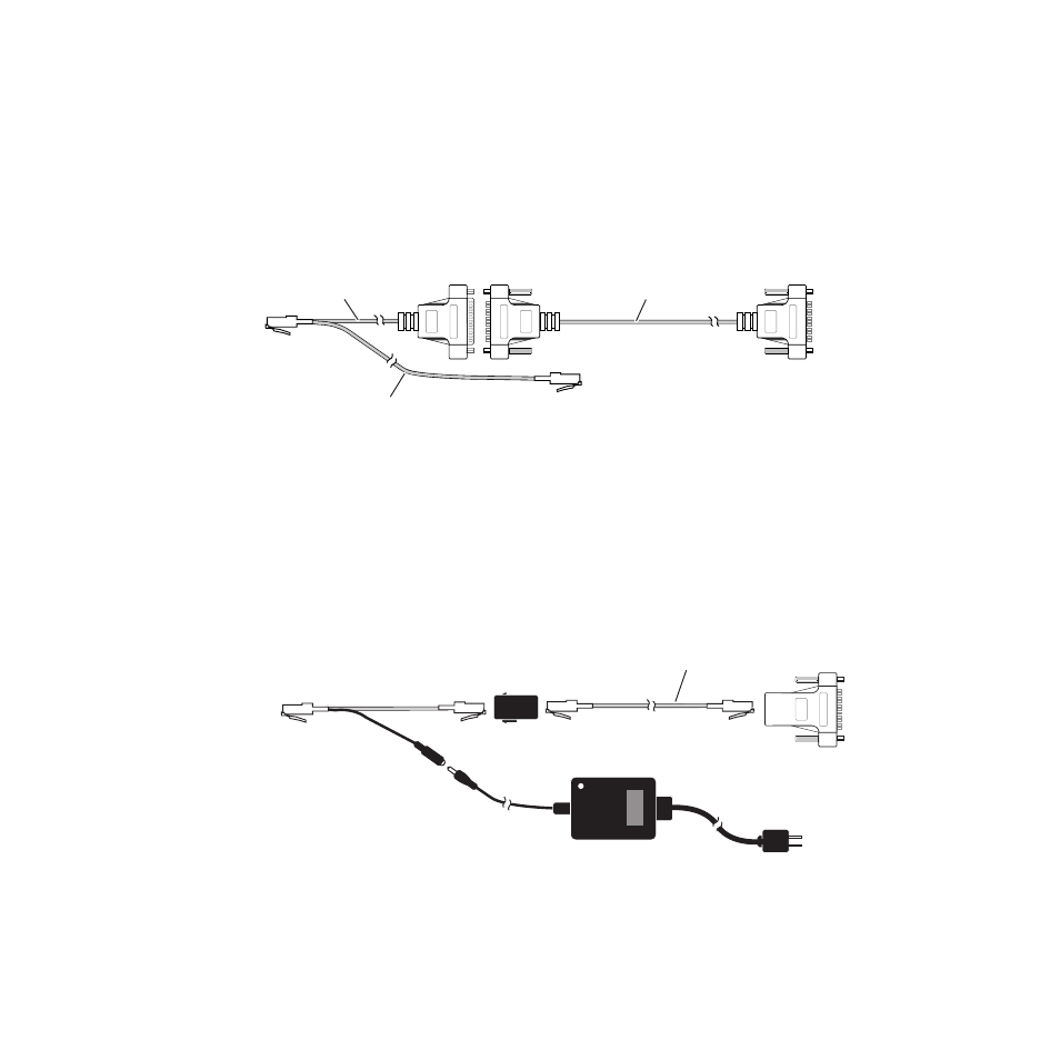
The cables provided connect the Main panel, Shot Box, and Video Pro-
cessor frame as shown in
. Power passes from the Main panel to
the Shot Box over this cable.
Note
When the fully functioning version of the Shot Box becomes available, the
RJ-45 port on the rear of the Shot Box will connect (via a 10 ft [3 m] cable
with RJ-45 connectors at both ends) to one of the Main panel Satellite ports.
Figure 34. Provided Shot Box Cables and Connections
Optional Satellite Panel Extension
If the Shot Box is to be placed more than 10 ft (3 m)
from the Main panel,
use an optional Satellite Panel extension kit, permitting installation up to
100 meters away. The kit consists of a Y-cable (to separate the communica-
tion path from the power path), a separate power supply, and two
adapters. A Cat-5 extension cable of the desired length is to be provided by
the end user. The Satellite Panel extension kit cabling replaces any existing
Shot Box cabling (
Figure 35. Shot Box Panel Extension Cabling, Editor Port Connection
Note
When the fully functioning version of the Shot Box becomes available, the
RJ-45 port on the rear of the Shot Box will connect to one of the Main panel
Satellite ports, and the 9-pin to RJ-45 adapter will not be used.
Male
To Video Processor
Frame Editor Port
16 m (52 ft)
To Shot Box
To Main Panel
Satellite Port
3 m (10 ft)
0619_05_07_r2
0.3 m (1 ft)
Female
Male
To Video Processor
Frame Editor Port (J11)
User Supplied Cat-5 Cable
100 meter maximum length
8159_00_01_r0
To Shot Box
Option Kit
Y-Cable
Plug
J2
9-Pin to RJ-45
Adapter
RJ-45
Barrel
Adapter
Power
Supply
To AC
Source