Figure 25, Table 5 – Grass Valley Zodiak Installation Planning Guide User Manual
Page 24
24
Zodiak Installation Planning Guide
Optional Components
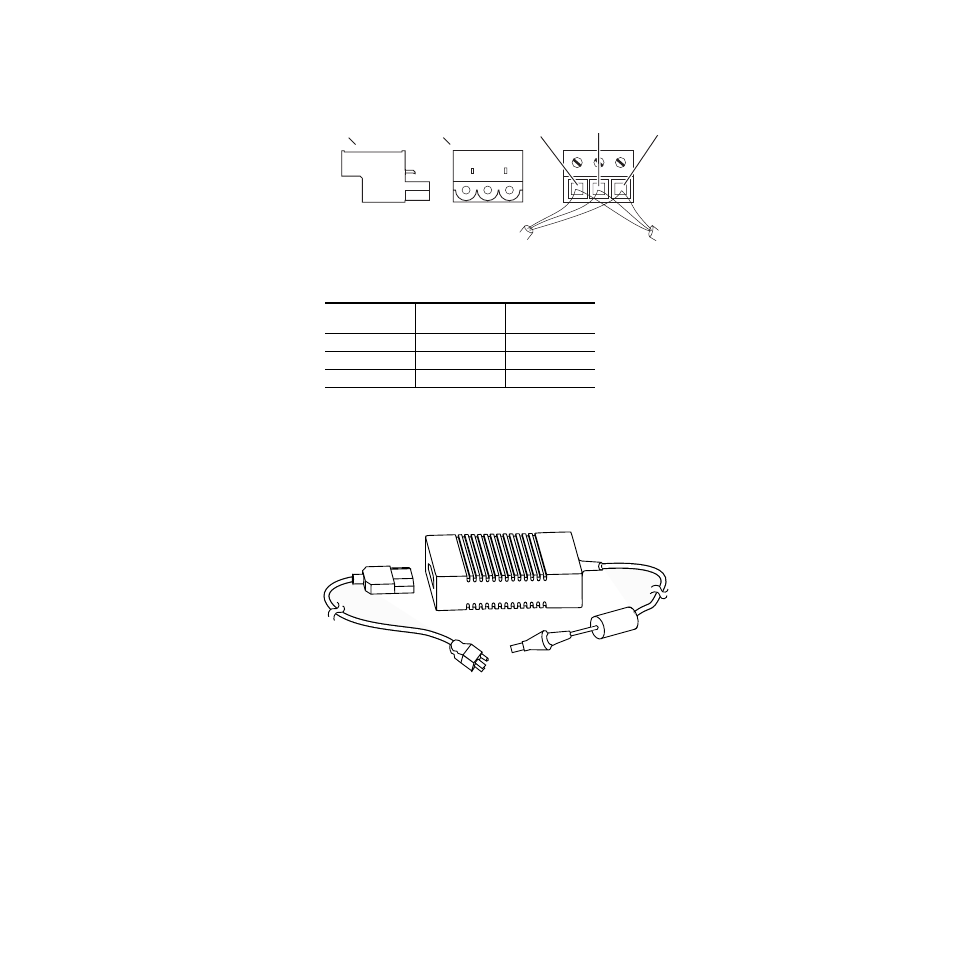
Figure 25. KAL-24 AUX Communications Bus Connector Cable Wiring
Power Supply
The 24-Crosspoint Remote Aux panel power supply (
) should
be securely fastened to a horizontal surface or attached to a support
inside the equipment rack. Verify that the power supply cord reaches
the 24-Crosspoint Remote Aux Control panel and the AC source.
Figure 26. KAL-24AUX Power Supply
Table 5. Cable Polarity
Panel
Connector
D-Connector
Pins
Factory Supplied
Cable
+ (Plus)
3 and 7
Red
- (Minus)
2 and 8
Black
Shield
9
Shield
0619_04_66_r0
To Pin 9 of
D Connector
(SHIELD)
To Pins 2 and 8 of
D Connector (–)
To Pins 3 and 7 of
D Connector (+)
To Next Panel
(If Any)
Side View
Connector-end
View
From Switcher or
Previous Panel
0619_04_63_r1
- LDK 5302 (24 pages)
- SFP Optical Converters (18 pages)
- 2000GEN (22 pages)
- 2011RDA (28 pages)
- 2010RDA-16 (28 pages)
- 2000NET v3.2.2 (72 pages)
- 2000NET v3.1 (68 pages)
- 2020DAC D-To-A (30 pages)
- 2000NET v4.0.0 (92 pages)
- 2020ADC A-To-D (32 pages)
- 2030RDA (36 pages)
- 2031RDA-SM (38 pages)
- 2041EDA (20 pages)
- 2040RDA (24 pages)
- 2041RDA (24 pages)
- 2042EDA (26 pages)
- 2090MDC (30 pages)
- 2040RDA-FR (52 pages)
- LDK 4021 (22 pages)
- 3DX-3901 (38 pages)
- LDK 4420 (82 pages)
- LDK 5307 (40 pages)
- Maestro Master Control Installation v.1.5.1 (455 pages)
- Maestro Master Control Installation v.1.5.1 (428 pages)
- 7600REF Installation (16 pages)
- 7600REF (84 pages)
- 8900FSS (18 pages)
- 8900GEN-SM (50 pages)
- 8900NET v.4.3.0 (108 pages)
- Safety Summary (17 pages)
- 8900NET v.4.0.0 (94 pages)
- 8906 (34 pages)
- 8911 (16 pages)
- 8900NET v.3.2.2 (78 pages)
- 8914 (18 pages)
- 8912RDA-D (20 pages)
- 8916 (26 pages)
- 8910ADA-SR (58 pages)
- 8920ADC v.2.0 (28 pages)
- 8920ADC v.2.0.1A (40 pages)
- 8920DAC (28 pages)
- 8920DMX (30 pages)
- 8920ADT (36 pages)
- 8920MUX (50 pages)
- 8921ADT (58 pages)