6riwzduh 6hwxs dqg 2shudwlrq – Grass Valley XSwitch Feb 01 2005 User Manual
Page 21
©2001 XSWITCH Installation and Operations Manual 19
6RIWZDUH 6HWXS DQG 2SHUDWLRQ
2SHUDWLRQDO 2YHUYLHZ
This overview presents a brief description of the XSWITCH’s operation, including a summary of the opera-
tional modes, as well as an overview of the main control panel, the status display and the special function
keys.
SYSTEM ACCESS AND SETUP
Powering the XSWITCH on is done by turning on both power supply switches on the rear panel. Both
switches will illuminate when on. Following power-up, the XSWITCH will initialize itself. Once initialized,
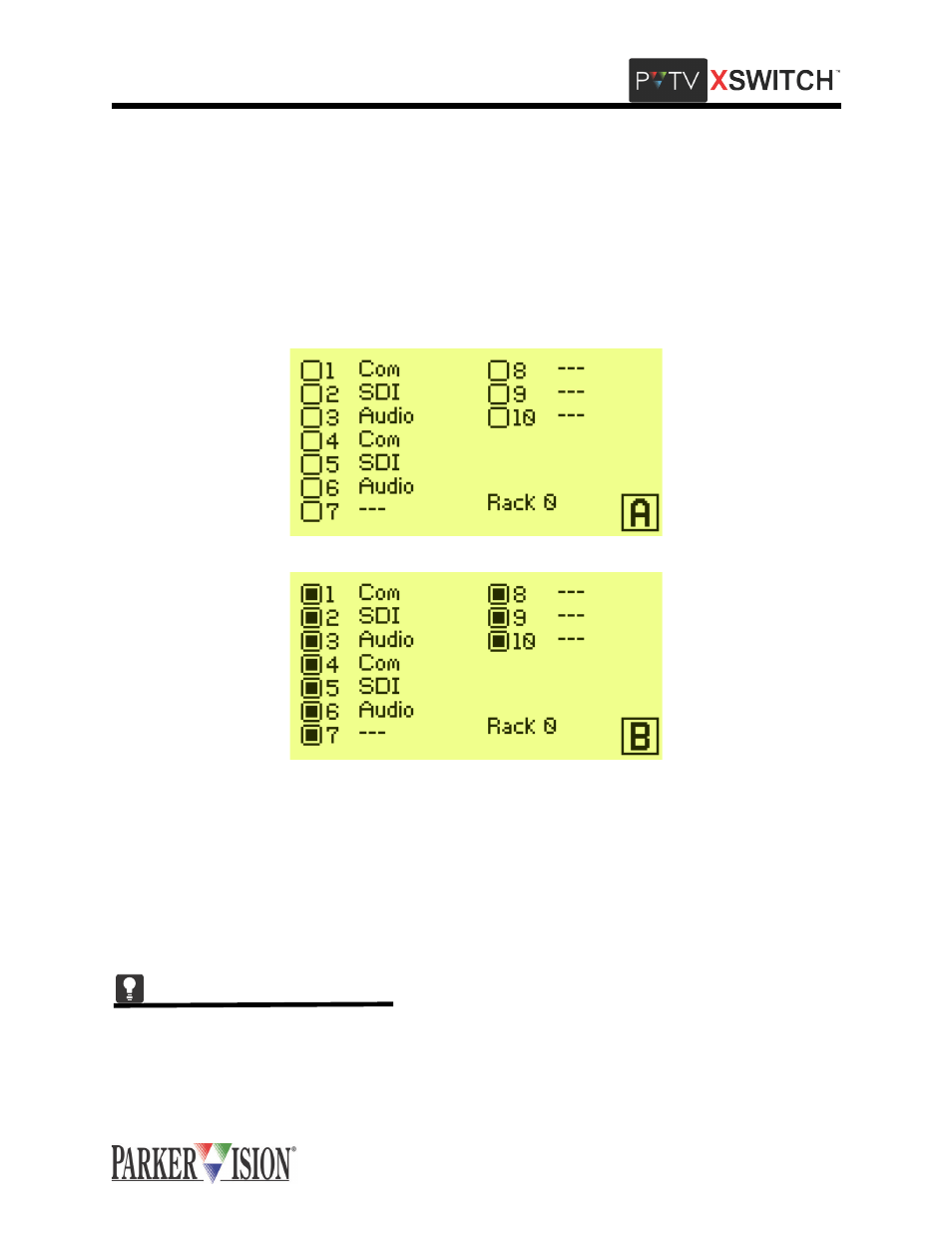
the system will display the Main Screen, which provides Switch Card Status information:
The icon in the bottom right corner indicates the current mode selection (A,B,C,D,or E).
To the left of this icon is the rack cage currently being displayed. In this case, Rack 0. The Master Module
is Rack 0. To switch to another rack, Use the Function Up and Function Down buttons.
Each slot in the module is listed (1-10). To the right of each card slot number is a short description of the
card type in that slot. To the left of the card slot is a radio button indicating the status of that card (on/off).
If the radio button is hollow, the corresponding Switch Card is off. If the radio button is solid-filled, the cor-
responding Switch Card is on.
To change from the Master Module to an Expansion Module, the mode select buttons on the front panel of
the XSWITCH may be used anytime.