Gpi i/o module – Grass Valley Kaleido-MX 4K (1RU) v.7.80 User Manual
Page 25
11
Kaleido-MX 4K (1RU)
Hardware Description & Installation Manual
The following table lists the function of each connector associated with the input modules.
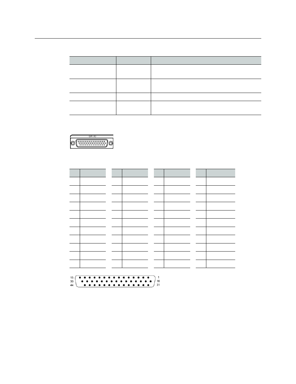
GPI I/O Module
The GPI-1501 module supports 20 GPI inputs, and 8 configurable GPI input/output
terminals. The pinout of the associated DB-44 connector, labelled GPI-I/O, is as follows:
GPI-I/O connector layout
For ease of connection, you may use the GPI-1501-TBA terminal block adapter with integral
44-pin connector. Refer to the GPI-1501 Guide to Installation and Operation (available on the
Kaleido-X DVD that shipped with your system, and from the Documentation Library section
of Grass Valley’s website), for more information. Refer to the Kaleido-X User’s Manual for
detailed instructions on configuring a GPI-1501 within your multiviewer system.
Connector label
Connector type Function
3G/HD/SD IN 1 to
3G/HD/SD IN 16
DIN 1.0/2.3
SD-SDI, HD-SDI, or 3G-SDI video inputs
ABT/MADI IN
DIN 1.0/2.3
Multiplexed audio from an external device (Audio
Bridge Terminal)
LTC IN
DIN 1.0/2.3
Time code input
REF IN
DIN 1.0/2.3
Reference signal to genlock the multiviewer to the
local plant.
Pin Signal
Pin Signal
Pin Signal
Pin Signal
1
GPIO-1 +
12
GPI-I 7
23
RS422-TX +
34
GPIO-5 –
2
GPIO-3 –
13
GPI-I 4
24
GPI-I 19
35
GND
3
GPIO-4 +
14
GPI-I 1
25
GPI-I 17
36
GPIO-7 +
4
GPIO-6 –
15
GND
26
GPI-I 13
37
RS422-RX –
5
GPIO-7 –
16
GPIO-1 –
27
GPI-I 11
38
GPI-I 20 / LTC
6
GPIO-8 +
17
GPIO-2 +
28
GPI-I 8
39
GPI-I 16
7
RS422-TX –
18
GPIO-4 –
29
GPI-I 5
40
GPI-I 14
8
GPI-I 18
19
GPIO-5 +
30
GPI-I 2
41
GND
9
GPI-I 15
20
GPIO-6 +
31
GND
42
GPI-I 9
10
GPI-I 12
21
GPIO-8 –
32
GPIO-2 –
43
GPI-I 6
11
GPI-I 10
22
RS422-RX +
33
GPIO-3 +
44
GPI-I 3