Grass Valley Kaleido-MX 4K (1RU) v.7.80 User Manual
Page 17
3
Kaleido-MX 4K (1RU)
Hardware Description & Installation Manual
The table below indicates how the cards included in your Kaleido-MX 4K (1RU) are
distributed in the housing frame:
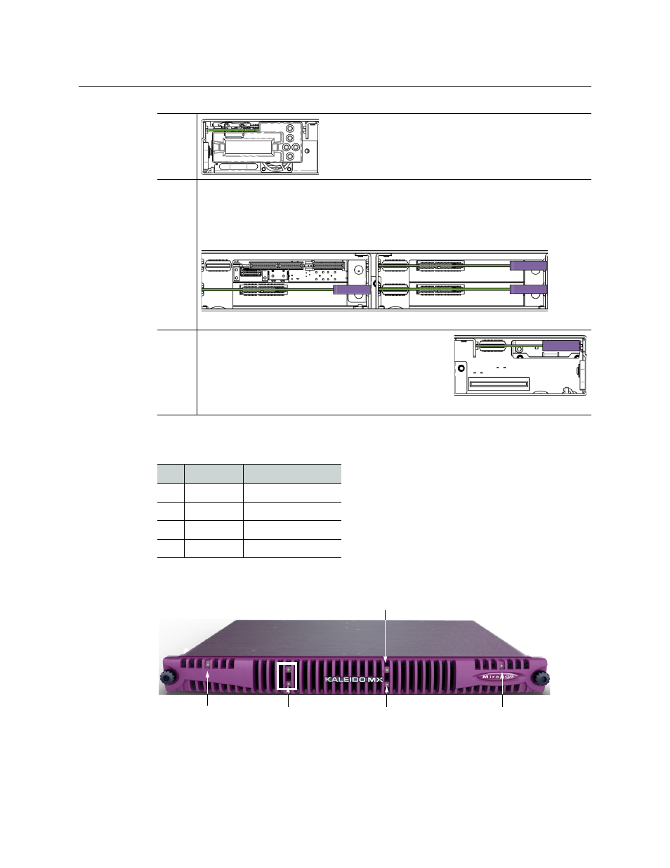
When the frame door is closed, the status LED on each of the cards in the frame is visible via
a light pipe in the door. No other controls or indicators are present.
Left
The controller card with its attached control panel is seen
on the left. The card itself is installed in a horizontal slot
near the top. A power supply is located below the
controller card in the frame.
Center Four card slots are laid out horizontally, two across by two down. Two output cards
occupy slots 3 and 4, on the right, and an input card occupies slots 1 and 2, on the
left. (The input card itself is inserted in slot 2, at the bottom.) The center area of a
Kaleido-MX 4K 16 × 1 system appears as follows:
Right
A second power supply is located on the lower right,
and above it is a single slot (slot 5) reserved for system
cards.
Note:
This slot supports ONLY designated system
cards; do not insert any other cards. At the time of
writing, only the GPI-1501 card is supported.
Slot Card
Card model
2
Input A
KMX-3901-IN-16-
Q
3
Output A
KMX-3901-OUT-D
4
Output B
KMX-3901-OUT-D
5
GPI I/O
GPI-1501
Slot 1 (empty)
Output card in slot 4
Output card in slot 3
Input card in slot 2
Controller card status
Input card status
GPI-1501 card status
Output A card status
Output B card status