Input modules – Grass Valley Kaleido-MX 4K (1RU) v.7.80 User Manual
Page 24
10
Installation
Input Modules
For more information about the serial ports’ specifications, see
, on page 34. For
more information about the RS-422 serial connections, see the “Serial Connections” section
in the Routers chapter of the Kaleido-X User’s Manual.
KMX-3901-OUT front card-edge USB connector
Every output module also has one USB connector, into which you may connect a mouse,
keyboard, or USB flash memory for a software upgrade or data backup. The diagram below
shows the USB connector, between various LED indicators and the Select button, on the
output cards’ front edge. See
Kaleido-MX 4K Output Card Interface
on page 20, for a
detailed description of the LED indicators, and
Using the Densité Frame Control Panel
page 22, for more information on the Select button.
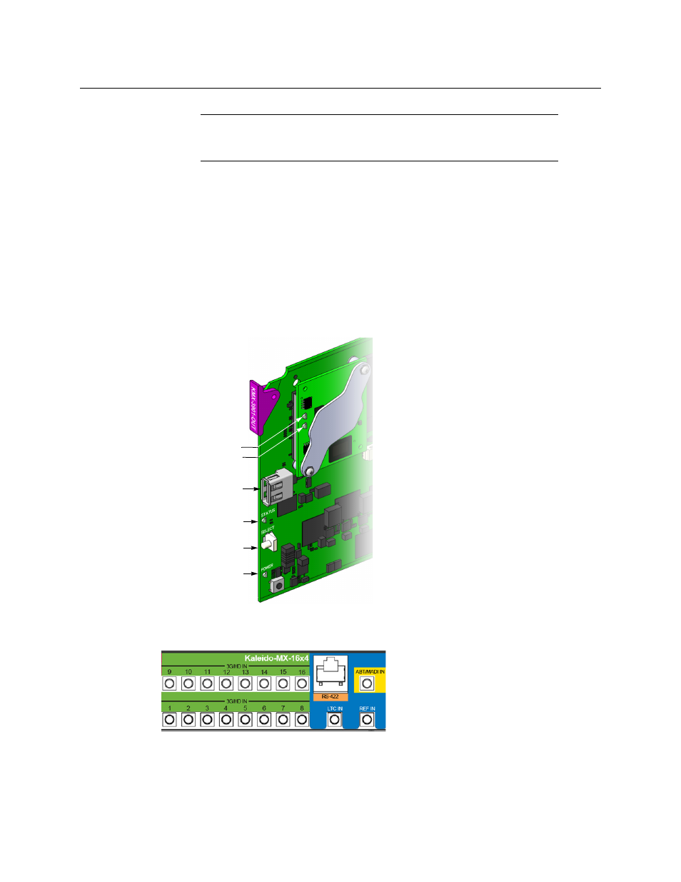
Input Modules
Input module connectors on Kaleido-MX 4K 16 × 1 (same rear panel as Kaleido-MX 16 × 4)
Note:
The multiviewer’s RS-422 port has no ground pin. Using the
appropriate DE-9S-to-RJ-45 adapter, an external device should be able to
communicate with a multiviewer despite the lack of a ground.
Status LED
Select button
Power LED
Output card
(bottom)
USB connector
Heartbeat LED
SD card access LED
Other side:
ETH com LED
(future use)
CPU 0 LED (not used)
CPU 1 LED