Page 9 – Grass Valley 3-CCD CameraMan Rev.B User Manual
Page 12
Page 9
Before you can begin to use your new Presenter Camera System, you need to configure its components.
There are two settings on the back of the Main Docking Station that must be set:
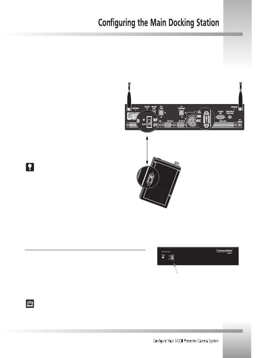
1. Set the RF CHANNEL switch to the desired channel. This
must match the setting on the Tracking Ring Power Pack. If
you experience any problems on one of the channels, switch
both to the alternate channel.
(Factory Default: UP position/ one dot)
2. Set the AUDIO LEVEL switch to the desired audio output.
To have a mic-level audio signal, set this switch to MIC.
To have a line-level audio output, set this switch to LINE.
This switch setting will apply to the balanced audio output only.
(Factory Default: MIC)
Refer to Appendix B for specifications on the audio outputs.
Step 2:
Audio Level Switch
Step 1:
RF Channel Switches must match
Switch the POWER button on the front of the Main Docking Station to ON. The
CameraMan camera should automatically enter its position calibration mode and then
stop at the zero degree point. Verify that the base is now facing in the direction you
pointed the FRONT label when mounting.
For more information on mounting the CameraMan, see the Installation and
Operations Manual that came with the camera.
Powering Up
Before you can configure the rest of your Presenter Camera System, you need to
turn on the systems power.
Main Docking
Station Power
Switch