Installation, Frame capacity, Module placement in the 8900 frame – Grass Valley 8990ARC v.1.0 User Manual
Page 8
2
8990ARC Instruction Manual
8990ARC SD Aspect Ratio Converter
Installation
Installation of the 8990ARC module is a process of:
■
Placing the module in the selected frame slot, and
■
Cabling and terminating signal ports.
The 8990ARC module can be plugged in and removed from an 8900 Series
frame with power on. When power is applied to the module, LED indica-
tors reflect the initialization process (see
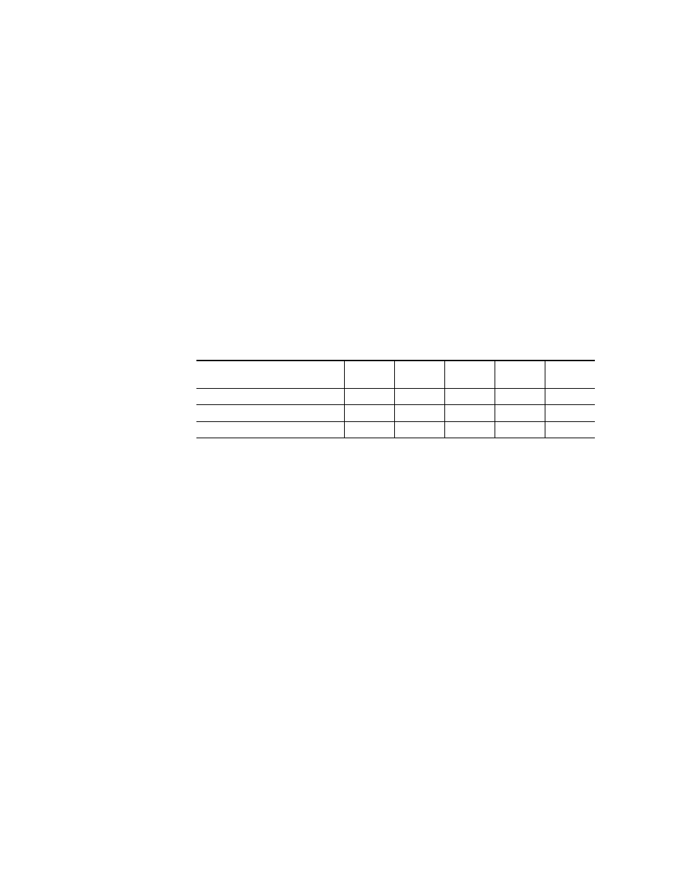
Frame Capacity
The maximum number of 8900 modules allowed in a frame is determined
by frame cooling capacity.
provides the power capacity, cooling
capacity, and maximum module count for the 8990ARC in each frame type.
Note
Module capacity figures assume no other modules are in the frame.
If the maximum number of modules a frame can handle is less than ten,
provide as much space between the modules as possible.
Module Placement in the 8900 Frame
There are ten cell locations in the frame to accommodate either analog or
digital modules. These are the left ten locations. Refer to
The two cells on the right are allocated for the power supplies. For addi-
tional information concerning the Power Supply module, refer to the 8900
Power Supply manual.
The third cell from the right is allocated for the Frame Monitor or Network
Interface module. These modules provide health bus monitoring and
control options.
Table 1. Power, Cooling, and Module Capacity of 8900 Frames
Capacity Calculated
8900T2
Frame
8900T2-F
Frame
8900TX
Frame
8900TF
Frame
8900TFN
Frame
Power (W)
60
60
100
100
100
Recommended Module Cooling (W)
30
60
30
90
90
8990ARC Modules
6
10
6
10
10