Grass Valley 8990ARC v.1.0 User Manual
Page 12
6
8990ARC Instruction Manual
8990ARC SD Aspect Ratio Converter
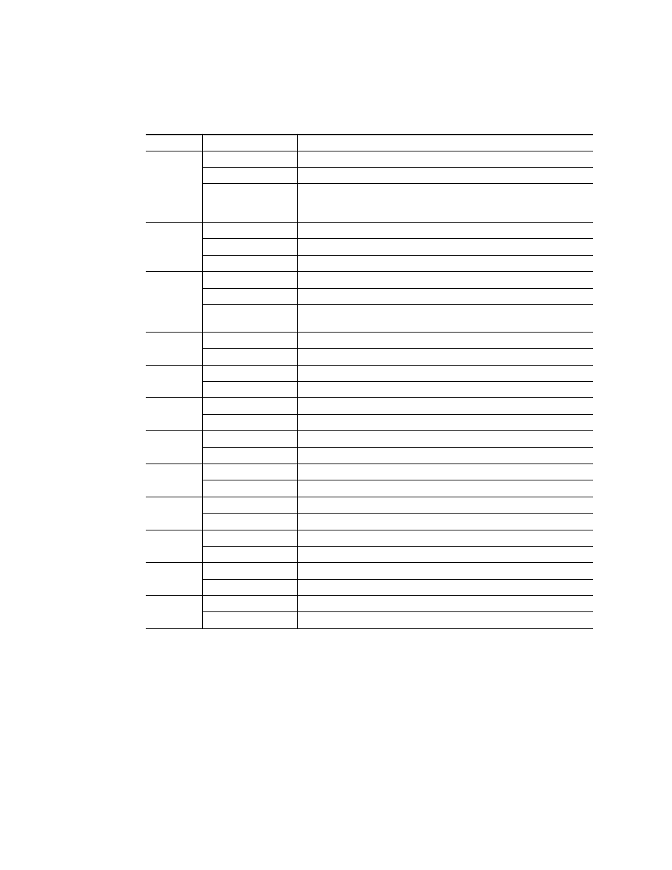
Table 2. Indicator LEDs and Conditions Indicated
shows the output formating control options and the
resultant output processing for various input signals and controls enabled.
LED
Indication
Condition
Fault
(red)
Off Normal
operation
On continuously
Module has detected internal fault
Short flash
EDH errors will cause short flashes. In most applications a few, infrequent EDH
errors will not be of consequence. Continuous EDH errors result in obvious output
signal degradation.
COMM
(yellow)
Off
No activity on frame communication bus
Long flash
Location Command received by the module from a remote control system
Short flash
Activity present on the frame communication bus
CONF
(yellow)
Off
Module is in normal operating mode
On continuously
Module is initializing, changing operating modes or updating firmware
Flashing
Indicates rate of change of paddle switch controlled analog setting. The longer the
switch is held, the more the flashing rate and the change-of-setting rate increases
PWR
(green)
Off
No power to module or module’s DC/DC converter failed
On continuously
Normal operation, module is powered
525
(green)
Off
Input signal is 625 standard or no signal is present
On continuously
Input signal is 525 standard and present
625
(green)
Off
Input signal is 525 standard or no signal is present
On continuously
Input signal is 625 standard and present
16:9
(yellow)
Off
4:3 mode is selected
On
16:9 mode is selected
4:3
(yellow)
Off
16:9 mode is selected
On
4:3 mode is selected
Mode 1
(yellow)
Off
Another mode is selected
On
Mode 1 is selected
Mode 2
(yellow)
Off
Another mode is selected
On
Mode 2 is selected
Mode 3
(yellow)
On
Another mode is selected
Off
Mode 3 is selected
On
Mode 4
(yellow)
Another mode is selected
Off
Mode 4 is selected