Cabling, Loop-through input, Outputs – Grass Valley 8990ARC v.1.0 User Manual
Page 10: General purpose interface (gpi) connections
4
8990ARC Instruction Manual
8990ARC SD Aspect Ratio Converter
Cabling
Loop-through Input
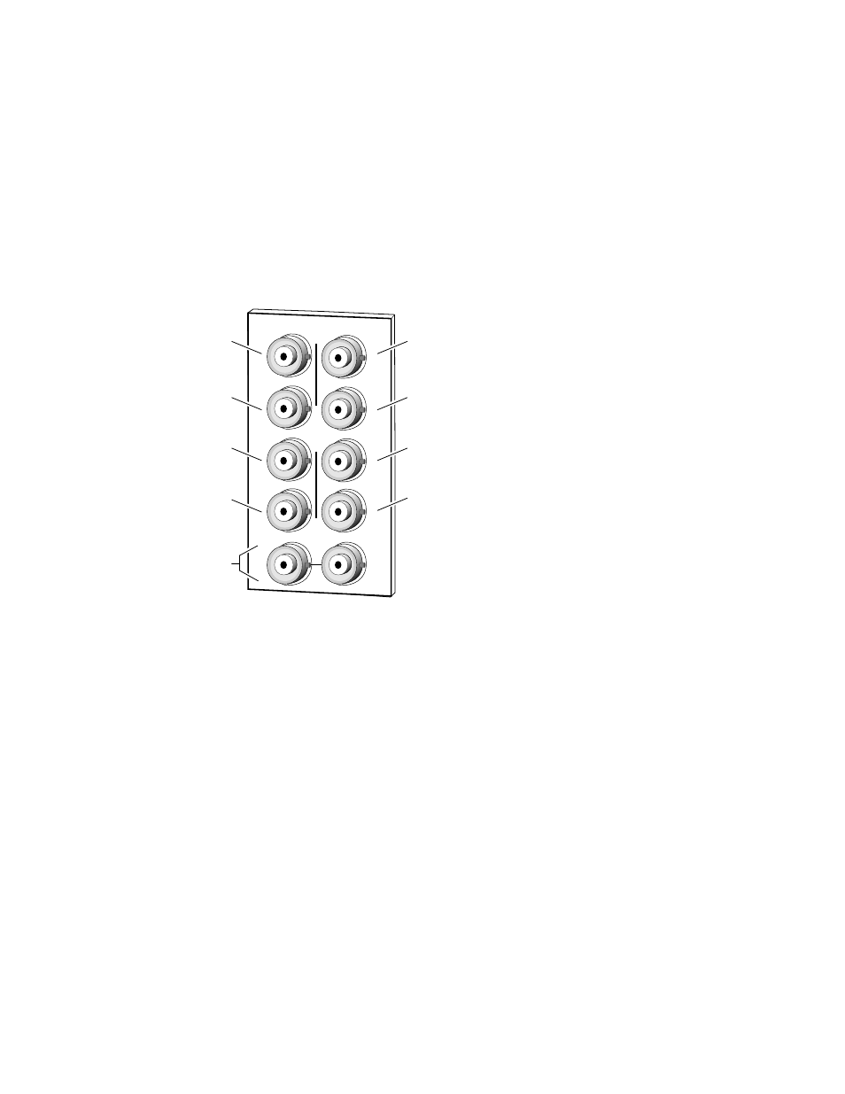
Connect an input source to one of the loop-through input connectors, J9 or
J10 (see
). The 8990ARC input accepts SMPTE 259M 8 or 10-bit
component serial digital video. Terminate the unused connector into 75
Ω
if
the signal is not looped to other equipment.
Figure 3. 8990ARC Input, Output and GPI Connectors
Outputs
The 8990ARC provides four 75
Ω
component video output BNCs (J1
through J4).
The destination equipment should have a 75
Ω
input impedance or loop
through inputs that are terminated into 75
Ω
.
General Purpose Interface (GPI) Connections
BNCs J7 and J8 accept GPI control signals that select one of four user-
defined preset settings that are stored using the onboard configuration con-
trols or the remote GUI controls. The GPI can be used with a user-provided
panel with four latching momentary switches and appropriate resistors.
No tally is provided from the module (see
).
J2
J4
J6
J8
J9 J10
IN
GPI
DAx
O
U
T
J3
J5
J7
J2
J1
J4
J6
J8
8036-02
Loop-through
SDI 270 Mbps Input
Output
Output
Not used
Output
Output
Not used
GPI