Video index coding, Wide screen signaling (wss), Gpi control – Grass Valley 8990ARC v.1.0 User Manual
Page 18: Om the module (see
12
8990ARC Instruction Manual
8990ARC SD Aspect Ratio Converter
Video Index Coding
In the video input signal, video source data can be inserted (on lines 11 or
324 for 625, on 14 or 277 for 525) to identify the signal line standard and
aspect ratio (per SMPTE RP-186 specification). If this information is present
and the 8990ARC Video Index function is enabled and the module output
mode matches the input, the module will pass the signal as is. If the output
mode does not match, the module will use the selected conversion mode
(2, 3, or 4). The Video Index coding is passed through to the 8990ARC
output unaltered.
Wide Screen Signaling (WSS)
In 625-line systems the video input signal can contain video source data on
line 23 (per specification EN 300 294 v1.3.2). If WSS is enabled, the
8990ARC output conversion mode will be controlled according to this
input data. If Video Index Control is also enabled, the WSS control, when
present, will take precedence. WSS coding is passed through to the
8990ARC output unaltered.
GPI Control
A GPI control input can be connected to either J7 or J8 (not both) on the rear
panel. This is a loop-through input to an A/D converter and a 1.21 K
Ω
resistor to +5 V. When the module’s GPI function is enabled, the 8990ARC
software will recognize a GPI input voltage level to select one of four stored
user-defined modes. Looping the input to additional modules allows a
single GPI signal to set them all (up to 10 modules).
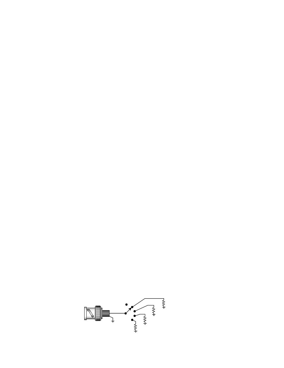
The GPI input is created by the application of a parallel resistor between the
coax center and common ground that results in a voltage lower than +5 V
to the A/D converter.
The following voltages (all ±0.4 V) will select the GPI register indicated:
■
1.25 V = GPI 1
■
2.08 V = GPI 2
■
2.92 V = GPI 3
■
3.75 V = GPI 4
The resistors required for these voltages are shown in
Figure 8. Typical GPI Input Circuit Diagram
1
2
3
4
402
Ω
Open
845
Ω
1690
Ω
3570
Ω
Connects to
J7 or J8
8036_07
Note:
Resistor tolerance = 1%
Only one GPI input can be used