Local onboard module configuration, Configuration switches and controls, D module configuration – Grass Valley 8981NR User Manual
Page 17
8981NR Instruction Manual
17
Configuration
Local Onboard Module Configuration
The 8981NR module can be configured locally using the rotary and paddle
switches. Several LEDs interact with the switches to indicate status of the
configuration process.
Configuration Switches and Controls
for the following descriptions. Use the onboard configu-
ration components as follows:
•
Function (rotary) switch – this switch accesses a desired function for
configuration (see
). The switch addresses two banks
of functions; each bank has 16 possible positions (0 through 9 and A
through F). Not all positions are used.
The next bank of functions is accessed each time the Function switch
makes a complete revolution past zero (or back through F): While in
Bank 1, a complete revolution past zero accesses Bank 2; while in Bank
2, a complete revolution past zero accesses Bank 1 again. The yellow
2ND LED indicates which bank is currently being accessed.
Note
The Function switch should be kept in position 0 in any bank (parked) when
not in use to avoid any inadvertent change in configuration. Position 0 in each
bank is inactive.
•
2ND (second Function) yellow LED – when off, indicates that the rotary
switch is addressing the first bank of functions. When on, indicates that
the rotary switch is addressing the second bank of functions.
•
Paddle switch – actuates or selects the desired setting for the selected
function when the switch is held momentarily in either the up or down
position.
•
CONF (configuring) yellow LED – when on, indicates the module is ini-
tializing or processing configuration information.
•
Jumper JP5 allows or locks out (Local) remote control.
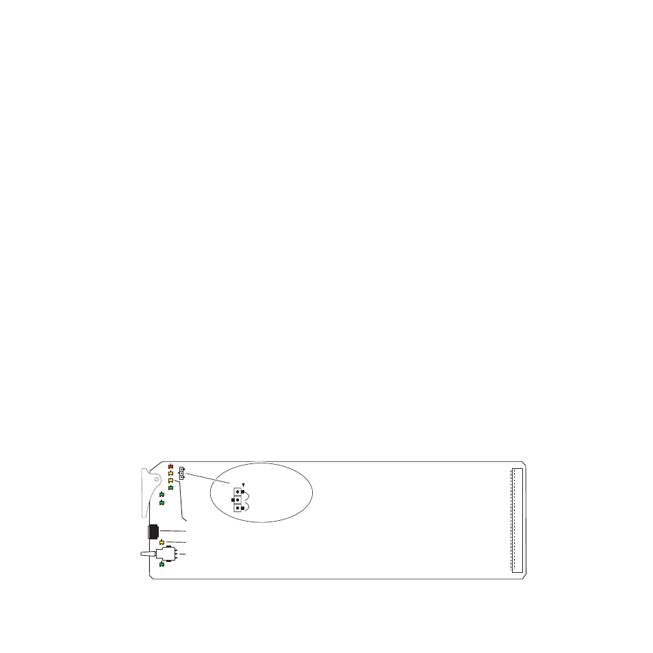
Figure 5. Module Configuration Switches and LEDs
8226_08
Place jumper in Local position
to lock out remote access.
Function rotary switch
2ND Function LED
CONF LED
Paddle switch
LCL&REM (2–3)
Remote Lockout
LOCAL (1–2)
JP5
JP5