Cabling, Attenuation requirements – Grass Valley 8943FC User Manual
Page 23
8943FC — Instruction Manual
23
Installation
Cabling
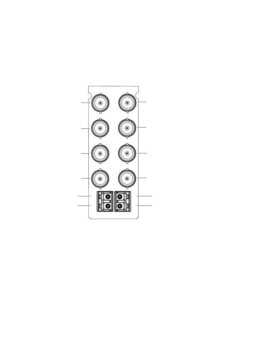
Cabling is done on the rear BNCs of the 8943FC-R module illustrated in
.
Note
Before making any fiber connections, refer to the
Figure 17. 8943FC-R Rear Module
Attenuation Requirements
Some shorter length cable runs will require attenuation to prevent over-
driving the receiver causing bit errors to occur on the fiber link. Use the fol-
lowing guidelines for adding attenuation:
•
The 1310nm Dual Transmitter (SFP-13103G-M1DTX) requires no atten-
uation between fiber transmitter and receiver connections at any cable
lengths.
•
CWDM devices used with 8939FCA modules for a mux/demux config-
uration (
) with a cable run from 0-12 km (7.5 miles), must be
attenuated by 3 dB between 8939FCA COM ports.
•
All CWDM devices used in a point-to-point configuration with a cable
run from 0-20 km (12.4 miles), must be attenuated by 5 dB between
fiber transmitter and receiver connections.
8771_02r0
8943FC-R
IN
IN
OUT A
OUT A
OUT A
OUT B
OUT B
OUT B
CH1
4
3
2
1
CH2
CH3
CH4
CH 1A Electrical Out
CH 1B Electrical Out
CH 1 Fiber In
CH 2 Fiber In
CH 2A Electrical Out
CH 2B Electrical Out
CH 3B Electrical Out
CH 3A Electrical Out
CH 3 Fiber In
CH 4 Fiber In
CH 4A Electrical Out
CH 4B Electrical Out