Grass Valley 8943FC User Manual
Page 19
8943FC — Instruction Manual
19
Installation
Channel 3 and Channel 4 SFP Device and Fiber Cable Installation
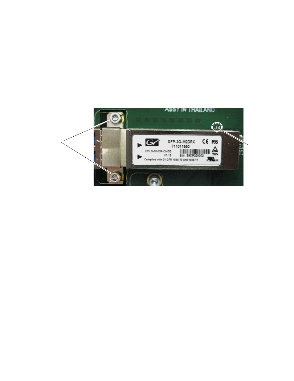
Repeat the SFP device installation procedure for the second SFP device in
the top SCA-2 connector, J4, of the module. This SFP device is also a dual
receiver with the same part number as the SFP device in J6.
Follow the instructions for installing the SFP device in connector J4 in the
same manner as the instructions for J6 starting on
steps 1 through 5. The finished installation of the Fiber Channel 3 and Fiber
Channel 4 SFP device should resemble the one in
.
Figure 11. SFP Device Installation for Ch 3 and Ch 4
Now install the Fiber Channel 3 and 4 fiber cable assembly from the SFP
device to the rear connector as described below.
1.
Remove the dust covers from the fiber cable assembly connectors to
expose the LC ferrules (the ends of the fiber optic cable).
2.
Clean the LC ferrules of the connectors (and after every de-mating
cycle) using an industry standard fiber optic cleaning kit as described
in
. Also visually inspect the LC ferrules for
damage or blockage before installing them into the SFP device.
3.
Remove the rubber dust cover from the SFP device connector end.
Insert the duplex end of the fiber cable assembly (the two fiber optic
cables connected together) into the SFP device by holding the strain
relief boot directly behind the connector housing as shown in
. Push on the strain relief until you hear a click, indicating the
connectors are properly mated.
Slide bracket straps
under screws
and tighten.
SCA-2
connector, J4