Onboard 8910ada-sr configuration, Befor – Grass Valley 8910ADA-M User Manual
Page 24
24
8910ADA-M/ST/SR — Instruction Manual
Module Configuration
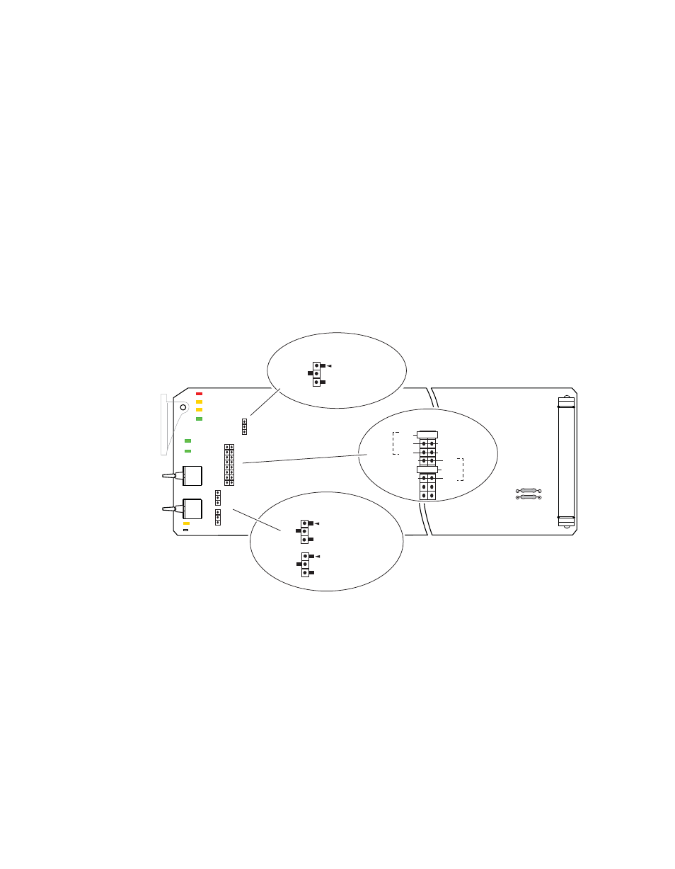
Onboard 8910ADA-SR Configuration
Onboard configuration of the -SR version includes:
•
Remote control enable/disable,
•
Output mode select, including summing, for each channel,
•
Overall gain and balance adjustment with the paddle switches,
•
Fine gain and balance adjustment with the hard-wired customer-sup-
plied potentiometers, and
•
Input signal phase inversion for each channel.
Note
Change jumper settings only when module is removed from the frame.
for an illustration of the jumper settings.
Figure 11. 8910ADA-SR Jumper Settings
8156_07
r2
SW2
SW1
Balance
Paddle
Gain
Paddle
F1
F2
In 1
In 2
Sum
In 1
In 2
Sum
CHAN 1
CHAN 2
J4
J2
1
UP
DOWN
2
J3
P1
Output Mode Select
J2
Phase Inversion
Local/Remote
CHAN 1
INVERT
NORMAL
CHAN 2
LOC/POT – pins 1-2
LOC/REM – pins 2-3
1
2
3
J3
INVERT
NORMAL
1
2
3
J4
LOC/
POT
LOC/
REM
1
2
3
INVERT – pins 1-2
NORMAL – pins 2-3
INVERT – pins 1-2
NORMAL – pins 2-3