Press in the ejector tab to seat the module – Grass Valley 8910ADA-M User Manual
Page 12
12
8910ADA-M/ST/SR — Instruction Manual
Installation
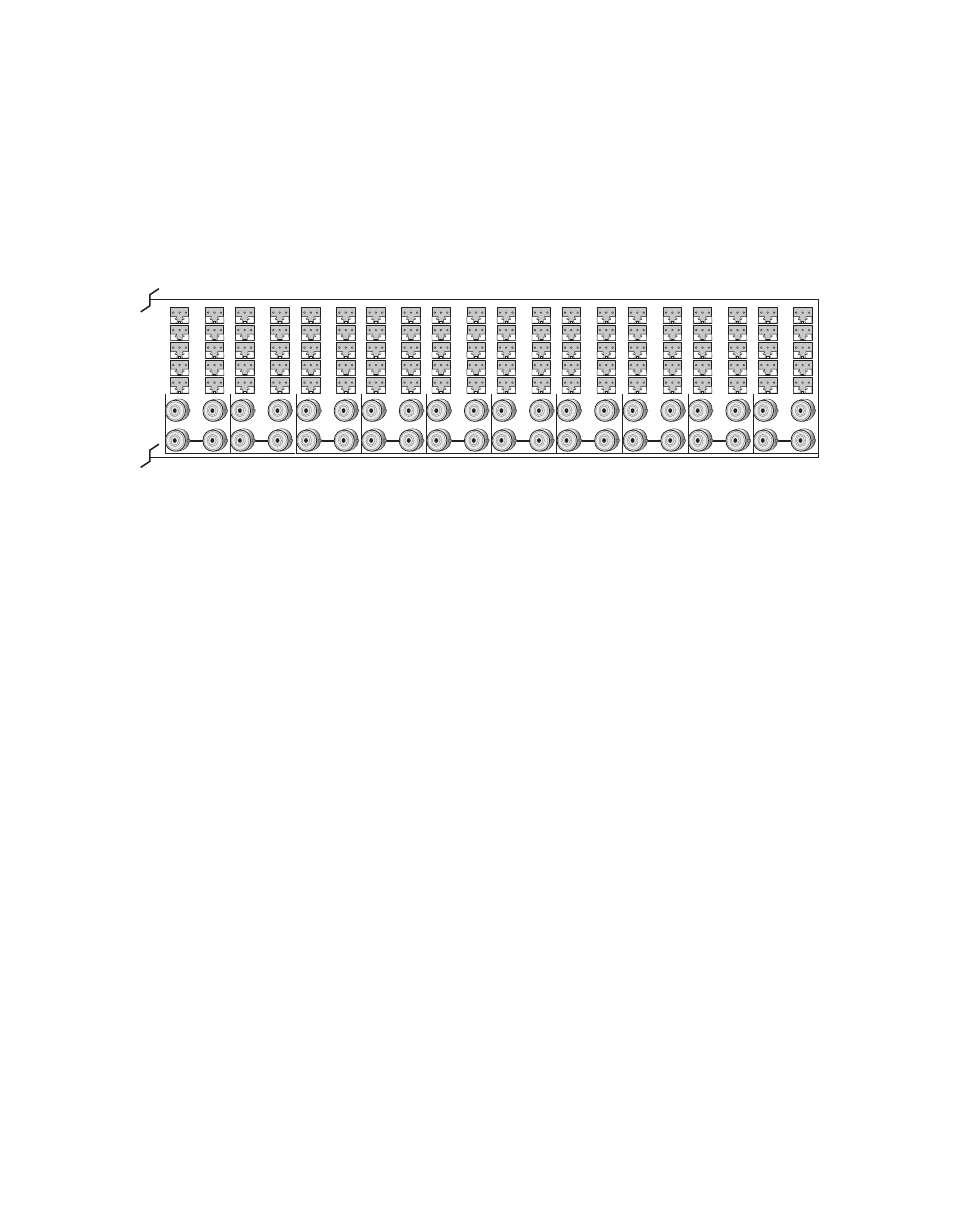
8900 module slots are interchangeable within the frame. There are 10
three-terminal connectors and 4 BNC connectors in each slot’s I/O group.
The functional assignment of each connector in a group is determined by
the module that is placed in that slot. The maximum number of modules an
8900 frame can accept is ten.
illustrates the rear connector plate for
an 8900 Series Audio frame.
Figure 2. 8900 Series Audio Frame Rear Connectors
To install a module in Gecko frame:
1.
If using local onboard controls, set jumpers on the module circuit
board. Refer to
Onboard 8910ADA-M and -ST Configuration on page 22
Onboard 8910ADA-SR Configuration on page 24
before installing the
front module.
2.
Insert the module, connector end first, with the component side of the
module facing to the right and the ejector tab to the top.
3.
Verify that the module connector seats properly against the backplane.
4.
Press in the ejector tab to seat the module.
8156_02
J1
J3
J5
J7
J9
J2
J4
J6
J8
J10
J11
J13
J12
J14
IN
1
J1
J3
J5
J7
J9
J2
J4
J6
J8
J10
J11
J13
J12
J14
IN
2
J1
J3
J5
J7
J9
J2
J4
J6
J8
J10
J11
J13
J12
J14
IN
3
J1
J3
J5
J7
J9
J2
J4
J6
J8
J10
J11
J13
J12
J14
IN
4
J1
J3
J5
J7
J9
J2
J4
J6
J8
J10
J11
J13
J12
J14
IN
5
J1
J3
J5
J7
J9
J2
J4
J6
J8
J10
J11
J13
J12
J14
IN
6
J1
J3
J5
J7
J9
J2
J4
J6
J8
J10
J11
J13
J12
J14
IN
7
J1
J3
J5
J7
J9
J2
J4
J6
J8
J10
J11
J13
J12
J14
IN
8
J1
J3
J5
J7
J9
J2
J4
J6
J8
J10
J11
J13
J12
J14
IN
9
J1
J3
J5
J7
J9
J2
J4
J6
J8
J10
J11
J13
J12
J14
IN
10