Onboard 8910ada-m and -st configuration, Monaural or stereo mode (-st module only), Refer to – Grass Valley 8910ADA-M User Manual
Page 22: Onboard 8910ada-m and -st configuration on
22
8910ADA-M/ST/SR — Instruction Manual
Module Configuration
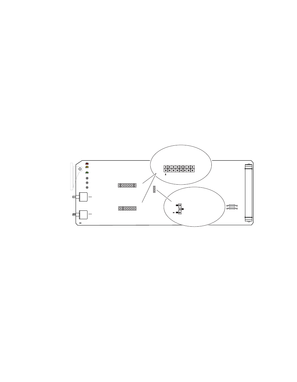
Onboard 8910ADA-M and -ST Configuration
The 8910ADA-M and -ST modules can be configured using the jumpers
and potentiometers shown in
These components perform the following:
•
Jumper blocks JP1 and JP2 (8910ADA-ST only) select the output gain
adjustment in increments of 6 dB.
•
Card edge potentiometers R5 and R6 (8910ADA-ST only) provide
greater than 6 dB gain adjustment within the jumper selected range.
•
Jumper JP3 (8910ADA-ST only) can be set to operate an 8910ADA-ST
module in Monaural or Stereo mode.
Note
Change jumper settings only when module is removed from the frame.
Figure 10. 8910ADA-M and -ST Module Configuration Switches and Jumpers
Monaural or Stereo Mode (-ST Module Only)
Set the module output to Monaural or Stereo with the following:
•
Jumper, JP3
STEREO – pins 1-2
MONAURAL – pins 2-3
8156_06
r1
F1
F2
Gain Ch. 1
potentiometer
Gain Ch. 2
potentiometer
R5
R6*
*R6, JP2, and JP3 are present
on stereo (ST) model only.
+30 db
+24 db
+18 db
+12 db
+6 db
0 db
-6 db
-12 db
JP1
JP2*
JP3*
Stepped Gain
Monaural/
Stereo Select
JP3*
2
1
15
16
STEREO
MONAURAL
(pins 1-2)
(pins 2-3)
S
TEPPED GAIN 1
S
TEPPED GAIN 2