Power up, Operation indicator leds – Grass Valley 8910ADA-M User Manual
Page 19
8910ADA-M/ST/SR — Instruction Manual
19
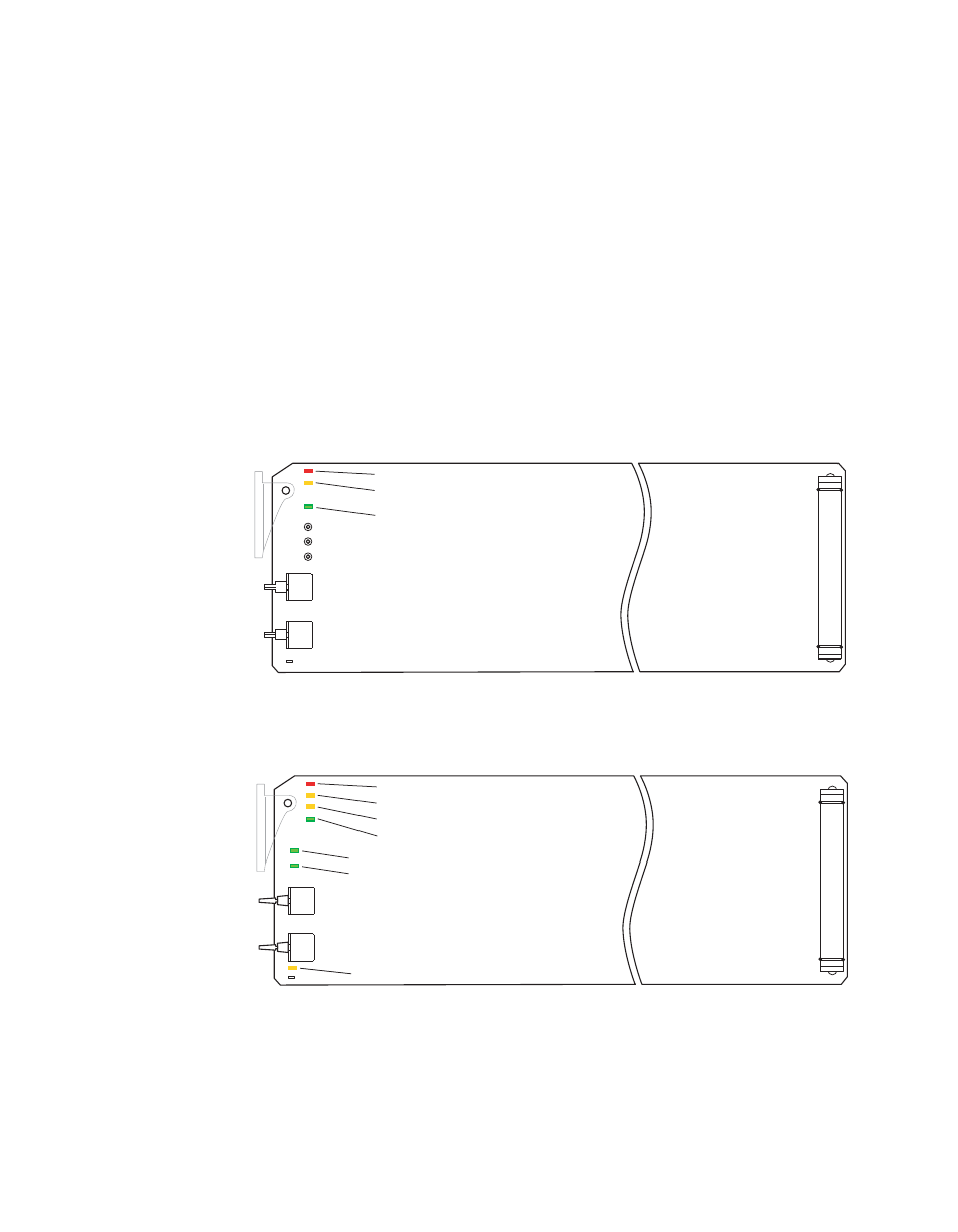
Power Up
Power Up
The front LED indicators for the -M and -ST versions of the module are
illustrated in
and the -SR version is illustrated in
. Upon
power-up, the green
PWR
LED should light and the red
FAULT
LED should
illuminate briefly for the duration of processor initialization.
Operation Indicator LEDs
With proper microprocessor supply voltage present (+5 V), the green
PWR
LED will be illuminated. The yellow
COMM
ED should illuminate when
communication to or from the module processor is detected.
A red
FAULT
LED indicates a processor error situation.
Figure 8. -M and -ST LEDs
Figure 9. 8910ADA-SR LEDs
8156_05
r1
R5
R6
FAULT (red)
COMM (yellow)
PWR (green)
OVR (yellow)
8156_08r1
FAULT (red)
COMM (yellow)
CONF (yellow)
PWR (green)
SW2
SW1
Channel 1 Present (green)
Channel 2 Present (green)