Hard-wired fine gain/balance potentiometer control – Grass Valley 8910ADA-M User Manual
Page 18
18
8910ADA-M/ST/SR — Instruction Manual
Installation
Hard-wired Fine Gain/Balance Potentiometer Control
On the 8910ADA-SR module only, BNCs J11 and J12 can be connected to
external hard-wired customer-supplied potentiometers for fine (± 6 dB)
gain and balance adjustment respectively. Overall gain and balance (-12 dB
to +30 dB) are set with the front edge paddle switches as explained below.
Note
The hardwired potentiometer controls are active only when the module is
jumpered for LOC/POT control. The Local/Remote position disables these
ports. Refer to
When both local paddle switch adjustments and hard-wired potentiometer
adjustments are made, the following input gain relationships exist:
•
Input 1 gain = hard-wired potentiometer gain + paddle switch gain -
paddle switch balance - hard-wired potentiometer balance
•
Input 2 gain = hard-wired potentiometer gain + paddle switch gain +
paddle switch balance + hard-wired potentiometer balance
These relationships will be reported on the Audio Status/Control web page
in read-only mode similar to the one shown in
. When
the gain or balance is changed using a paddle switch or one of the potenti-
ometers, the web page will update when the user manually refreshes it.
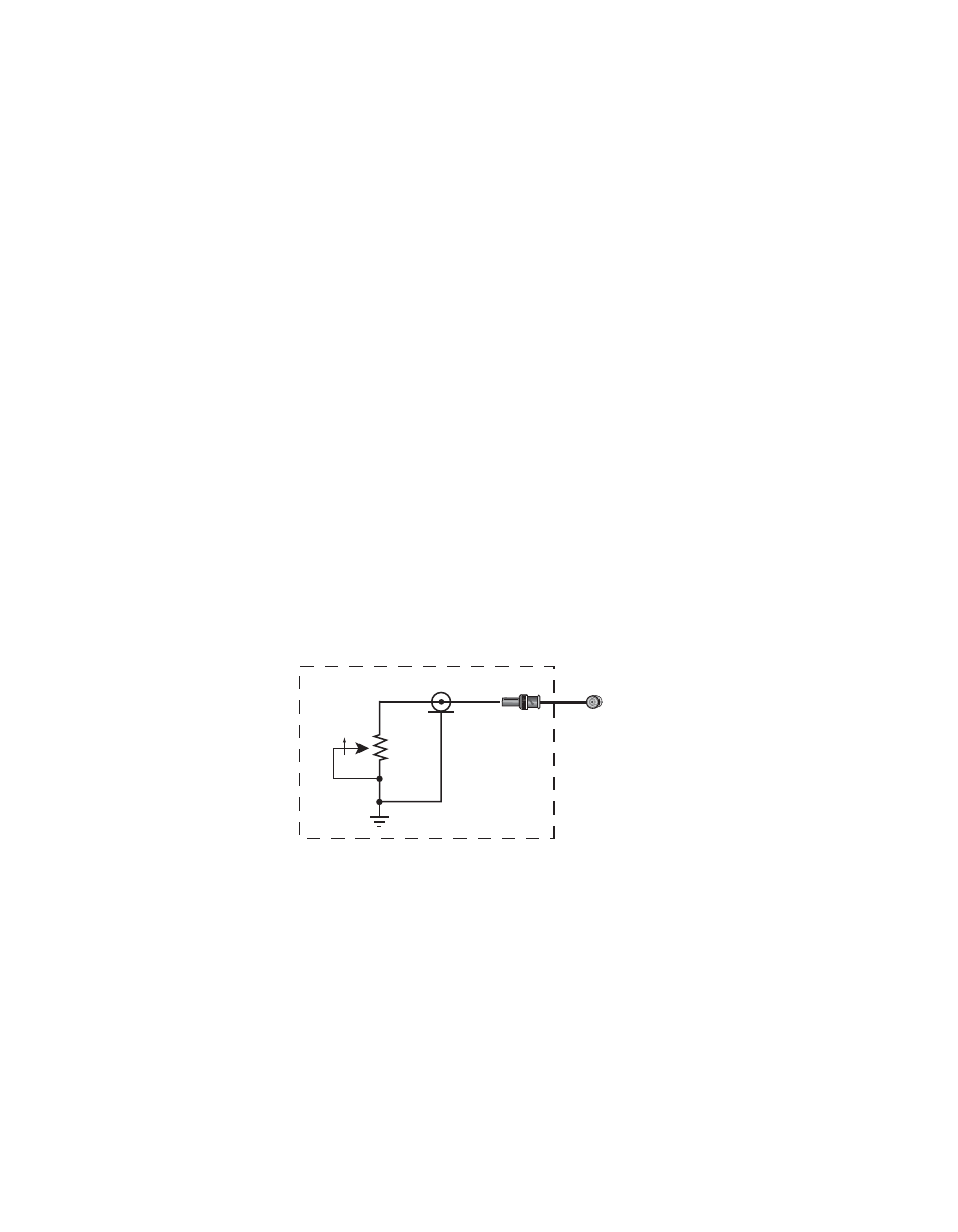
provides a schematic diagram for constructing a user-supplied
hard-wired control circuit to connect to these BNCs.
Figure 7. User-supplied Hard-wired Fine Gain and Balance Control Circuits
Connect to J11 for
potentiometer fine gain adjust
Connect to J12 for
potentiometer fine balance adjust
10 k
CW*
* Clockwise rotation increases gain for gain pot and
increases gain for channel 2 while decreasing gain
for channel 1 for balance pot.
8156_10r1