Layer 2 dynamic aggregation configuration example, Network requirements – H3C Technologies H3C SecPath F1000-E User Manual
Page 34
18
Configuring GigabitEthernet0/2... Done.
Configuring GigabitEthernet0/3... Done.
[DeviceA-Bridge-Aggregation1] quit
Step2
Configure Device B
Configure Device B using the same instructions that you used to configure Device A.
Step3
Verify the configurations
# Display summary information about all aggregation groups on Device A.
[DeviceA] display link-aggregation summary
Aggregation Interface Type:
BAGG -- Bridge-Aggregation, RAGG -- Route-Aggregation
Aggregation Mode: S -- Static, D -- Dynamic
Loadsharing Type: Shar -- Loadsharing, NonS -- Non-Loadsharing
Actor System ID: 0x8000, 000f-e2ff-0001
AGG AGG Partner ID Select Unselect Share
Interface Mode Ports Ports Type
-------------------------------------------------------------------------------
BAGG1 S none 3 0 Shar
The output shows that link aggregation group 1 is a load shared Layer 2 static aggregation group and
it contains three Selected ports.
Layer 2 Dynamic Aggregation Configuration Example
Network requirements
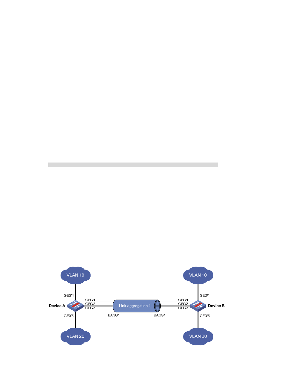
As shown in
:
•
Device A and Device B are connected through their respective Layer 2 Ethernet interfaces
GigabitEthernet 0/1 through GigabitEthernet 0/3.
•
Configure a Layer 2 dynamic aggregation group on Device A and Device B respectively, enable
VLAN 10 at one end of the aggregate link to communicate with VLAN 10 at the other end, and
VLAN 20 at one end to communicate with VLAN 20 at the other end.
Figure 5 Network diagram for Layer 2 dynamic aggregation