Configure the physical connection mode, Connect the cables – H3C Technologies H3C S5500 Series Switches User Manual
Page 55
47
Configure the physical connection mode
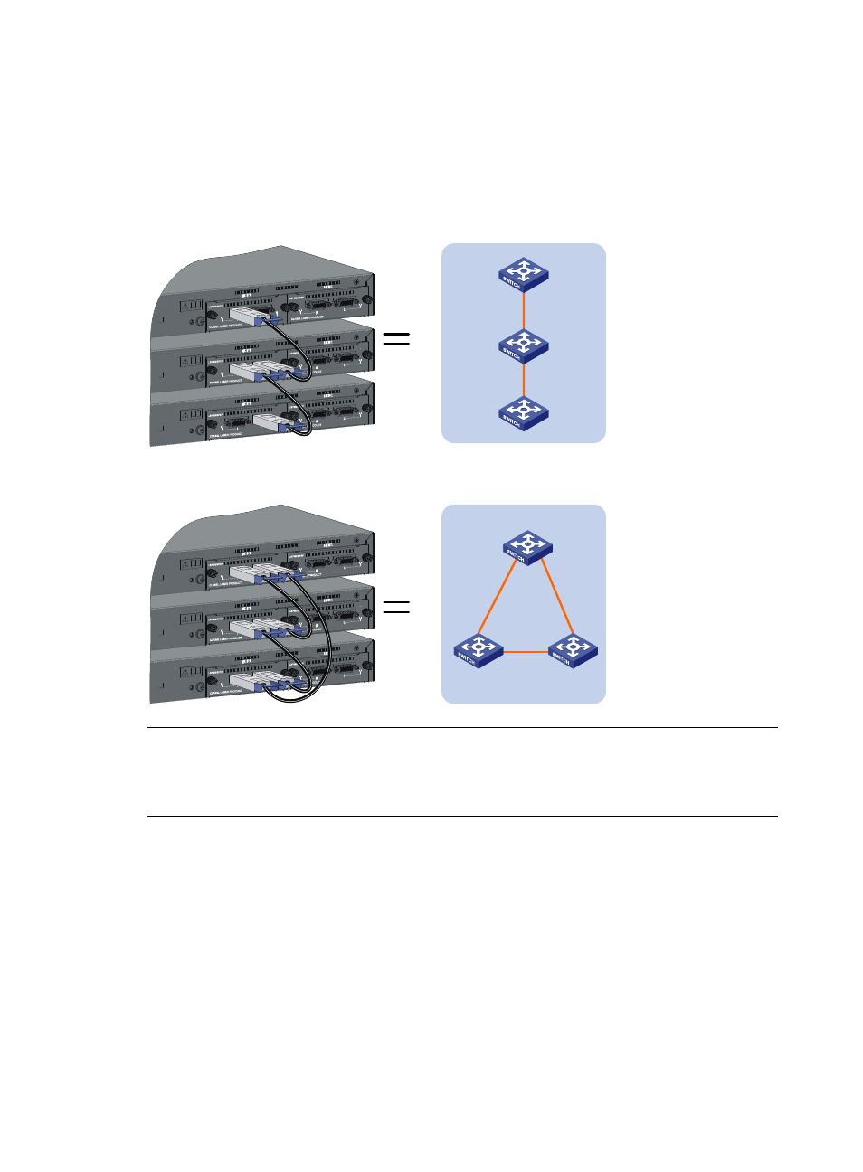
IRF supports two physical connection modes: daisy chain connection and ring connection.
A ring connection is more reliable than a daisy chain connection. The failure of one link in a ring
connection does not affect the function and performance of the IRF virtual device, whereas the failure of
one link in a daisy chain connection causes the split of the IRF virtual device.
Figure 45 The daisy chain connection mode
Figure 46 The ring connection mode
NOTE:
Each of the devices comprising a ring connection or non-edge devices in a daisy chain connection needs
two 10 GE ports to connect other devices; therefore, you need to install two 1-port 10 GE XFP interface
cards on such devices.
Connect the cables
Before connecting the cables, determine the actual position of the member devices and the length of the
cables, and observe the following:
•
Understand the neighbor devices for one another
•
Install the interface cards in proper slots as needed. Each S5500-EI series provides two expansion
slots.
•
Determine the ports on different devices to be connected.
When 2-port interface cards are used to constitute an IRF virtual device and the ports are not assigned
to any aggregation group, ports of the interface card in slot 1 (MOD 1) can be connected to ports of
MOD 1 or MOD 2. However, the left port can be connected to only the right port of another interface
card, that is, two ports at the same side cannot be connected, as shown in
Master
IRF virtual
device
Slave
Slave
Master
Slave
Slave
IRF virtual
device